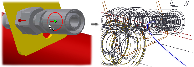
Use the New Route command with a flexible hose style active to add a flexible hose route to the active run. You can determine the location to store the flexible hose assembly to contain the hose route. It is recommended that you put all hose assemblies under the corresponding parent run.
Define the route by selecting the Route command from the Route tab, and then selecting two or more points. The route creation method varies depending on the number of fittings included in the style. To provide more control over route shape and direction, you can select intermediate route points using displayed tools as a guide. To create multiple intermediate points when you route a flexible hose with fittings, right-click in the graphics window and select Intermediate Point. You can place one fitting, construct the hose, and finish by placing the second fitting.
- Press CTRL to highlight a component in the graphics.
- Continue to hold down CTRL, right-click the component, and then select Find in Browser from the context menu. Inventor highlights the component in the browser.
Create a hose route with two fittings
- In the browser, activate the run to contain the new route.
-
 With a two-fitting style active, click
Pipe Run tab
 Route panel
 New Route .
- In the Create New Hose dialog box, provide a name and location for the hose subassembly file and click OK.
-
 On the ribbon, click
Route tab
 Create panel
 Route to begin routing.
- In the graphics window, select a location for the first fitting:
- To connect to another fitting, pause the cursor over the fitting, and then click to set the connection.
- To connect to a standard Autodesk Inventor part, pause the cursor over the part, and then click a circular edge.
- To place in the graphics window, click anywhere in the background.
Note: If needed, use the space bar, or right-click and select Next Connection to reverse the connection direction for the fitting. - Select a location for the second fitting.
Tip: Before placing the fitting you can flip the direction of the axis. To flip directions, press the spacebar or right-click, and then Select Other Direction from the context menu.
- If needed, insert any number of interior points. Click in sequence from the Start fitting to the End fitting or endpoint.
- To associate the point with existing geometry, select a vertex, work point, or center points on circular components.
- To offset a point at a specified distance, select a face or work plane.
As you make your selections a line appears from selected point to current cursor position. The system draws the line between the points as selections are made.
- To change the offset while pausing over a face, right-click and select Edit Offset.
- In the Edit Offset dialog box, enter the desired offset value (with or without a unit), and then click OK.
Once the offset is changed, the new value is used until the segment is finished or until the offset is changed.
Note: If no unit is specified the default unit setting is used. - When the segment shape is complete, right-click and select Done. Select Return or Finish Route to exit route mode.
The following image shows the resulting route when the initial route vector direction is correct.

This image shows the resulting route when the initial route vector direction is incorrect.

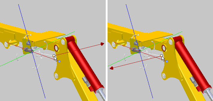
The following image shows two of the six possible coordinate directions for the route direction vector when you reference an existing work point. Pause the cursor over the work point, and then press the spacebar to cycle the vector directions.

 Show Me how to create hose with fittings
To find a flexible hose fitting in the browser
- Press CTRL to highlight a component in the graphics.
- Continue to hold down CTRL, right-click the component, and then select Find in Browser from the context menu. Inventor highlights the component in the browser.
Create a hose route with one or no fittings
When there is only one fitting used for the route, it must be the start fitting.
- In the browser, activate the run to contain the new route.
-
 With a one-fitting or no-fitting style active, click
Pipe Run tab
 Route panel
 New Route .
- In the Create New Hose dialog box, provide a name and location for the hose subassembly file and click OK.
-
 On the ribbon, click
Route tab
 Create panel
 Route to begin routing.
- In the graphics window, select a location for the hose start point or the first fitting.
- If needed, insert any number of interior points. Click in sequence from the start point or fitting to the endpoint.
- To connect to a fitting, pause the cursor over the fitting, and then click to set the connection.
- To associate the point with existing geometry, select a vertex, work point, or center points on circular components.
- To offset a point at a specified distance, select a face.
- To select a point interactively, use the 3D Orthogonal Route tool.
- Place the first fitting, then, right-click and select Intermediate Point to add additional points. After all desired points are specified, right-click and select Place End Fitting to place place a second fitting.
- Place both fittings and then construct a hose spline using Intermediate Point and/or Offset Point. Both of these options are available from the context menu and can be switched at any time.
Note: This workflow is unavailable if you have already constructed part of a spline after placing the first fitting.
To create multiple intermediate points or offset points when you route a flexible hose with fittings, right-click in the graphics window and select Intermediate Point and/or Offset Point. You can place one fitting, construct the hose, and finish by placing the second fitting. You can also place both fittings and construct the hose switching between Intermediate Point and Offset Point commands. For example:As you make your selections a line appears from selected point to current cursor position. The system draws the line between the points as selections are made.
- To change the offset while defining the segment path, right-click, and then select Edit Offset.
- In the Edit Offset dialog box, enter the desired offset value (with or without a unit), and then click OK.
Once the offset is changed, the new value is used until the segment is finished or until the offset is changed.
Note: If no unit is specified the default unit setting is used. - When the segment shape is complete select the endpoint, right-click and then select Done. Select Return or Finish Route to exit route mode.
To change the diameter for multiple fittings
When changing the diameter for one or multiple fittings, diameters that are common to all selected fittings and available from Content Center display the Select Diameter dialog box. You can select a new diameter from this list of available diameters.
- Activate the pipe run.
- In the graphics window or the Model browser, select the fittings to change. Press Ctrl or Shift to select multiple fittings.
- Right-click, and then select
Change Fitting Diameter.
Note: If there are no diameters in common, reduce the number of fittings in the selection, and repeat Steps 1 and 2 until one is found.
- Diameters that are common to all selected fittings and are available from Content Center display. In the Select Diameter dialog box, select a diameter to change the diameters of the selected fittings.
- Click OK.
