How to create these fundamental views, and to create drawing views from a model file.
What's New: 2018
Create and Edit a Base View
The Base View command by default selects the last active model document as the source for the placed view. If the last active model document is closed, no model is automatically selected.
- On the ribbon, click
Place Views tab
 Create panel
 Base
Base
 .
.
- In the Drawing View dialog box, on the Component tab:
- To specify the model, select a file from the list of open files, or click Open an existing file
 , and locate a model file.
Note: You can create a view of a part that contains only sketches. 2D sketches must be parallel to the view.
 - Depending on the file type, select the design view representation, positional representation, level of detail representation, sheet metal view, weldment group, or presentation view.
- Specify the view style. Choose from Hidden Line
 , Hidden Line Removed
 .
Note: The Shaded
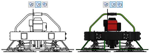
 option displays the model colors in the view. The following image shows a Hidden Line Removed view with the Shaded option OFF and with the Shaded option ON.

- Switch the visibility of the view label in the drawing on or off. To edit the view label in the Format Text dialog box, click Edit View Label.
- If appropriate, change the view scale.
- To specify the model, select a file from the list of open files, or click Open an existing file
- On the Model State tab, depending on the type of model, select iAssembly or iPart member, weldment state, or set the Reference Data options.
To extend the size of the view bounding box, increase the Margin value.

- On the Display Options tab, set display options for the view. Available options depend on the type of file used to create the view.
- In the graphics window:
- Move the base view to the appropriate location.
- Use the view cube to specify orientation of the model and type of projection.
- Drag a corner of the base view border to change view scale. By default, within the range of scales predefined in the current Standard style, the view size snaps to the preset scale values. Hold the CTRL key to enable free dragging, and set arbitrary view scale. When you change scale by free dragging, the Scale value displays as a real number in the Drawing View dialog box.
- Click the arrows on the base view to place the projected views. Click the x mark on a projected view to remove a projected view.
Note: When you edit a base view, the same options are available to change the view.
Create and Edit a Projected View
Projected views are generally the first type of view created from a base view. The projected view command creates orthographic and isometric views from a base view.
You can switch between first-angle and third-angle on the View Preferences tab of the Standard style. The change affects only the current drawing unless you save the setting to the style library. All other drawings that use that standard are updated with the changed projection.
You can create multiple views with a single activation of the command. Multiview projections are aligned to the parent view and inherit its scale and display settings.
Axonometric projections are not aligned to the parent view. They default to the scale of the parent view, but they do not update when you change the scale of the parent view.
In the preview, the orientation of projected view reflects its relationship to the parent view.
- On the ribbon, click Place Views tab Create panel Projected
 .
.
- Select the parent view for the projection.
- Move the preview to the appropriate location, and then click to place the view.
- Continue placing projected views by moving the preview and clicking.
- To quit placing projected views, right-click, and then select Create.
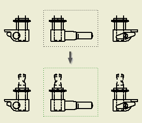
- (Optional) To switch on or off the inheritance of the section, slice, broken, or breakout cut, right-click the projected view, and select Edit View. Open the Display Options tab of the Drawing View dialog box, and select the appropriate options in the Cut Inheritance section.
Create Drawing Views from a Model File
Drawing creation from a model is supported in the following environments: Part, Weldment Assembly, Assembly, Presentation, Sheet Metal, and Flat Pattern. It also supports iPart, and iAssembly factories and member files.
When you create drawing from a model, the following model properties are automatically propagated from the model file to the base view:
- All active representations (design view, position, and level of detail representation)
- Current camera including Orthogonal/Perspective setting
- Active iPart/iAssembly member
- In the model file, arrange the model as desired.
- Right-click the root component in the browser, and click Create Drawing View.
- In the Drawing Template dialog box, select a drawing template to use, and click OK.
A drawing is created, and the Base View command is started. The current model state is propagated to the Drawing View dialog box, and a base view is placed on a drawing sheet.
- If appropriate, in the Drawing View dialog box, set the view properties.
- If appropriate, use the direct-editing tools in the graphic window to arrange the view, or to place projected views.
- Click OK to close the Drawing View dialog box.