You can move, rotate, resize, reposition sketched or placed features, and you can infer and create constraints in sketched features.
Move or Rotate Sketched or Placed Features
- Drag to relocate an extrude, revolve, or sweep feature, or use Triad Move option to enter precise coordinates relative to selected geometry.
 Show Me How to Use 3D Grips to Move a Feature
Resize Sketched Features

- Right-click the face of an editable face or feature, and click 3D Grips on the context menu.
- In the graphics window, move the cursor over a grip point on the feature to highlight direction arrows.
- Click a direction arrow and either:
- Drag to see a preview of the new size.
- Click a face, edge, vertex, or work feature to snap to the selected item.
- Continue to click and drag arrows to resize the face or feature. When dragging, the distance moved from the previous position displays.
- After you drag to a new size, if appropriate, right-click an arrow and enter values:
- For length, choose Edit Offset or Edit Extent. Enter a value.
- For width or radius, choose Edit Offset or Edit Radius. Enter a value.
The feature previews the expected results before you commit to the change.
- To quit, right-click, and select Done.
Resize Placed Features
- To resize a placed feature, use its respective dialog box, such as the Hole dialog box, to enter values.
Reverse direction of a Sketched Feature
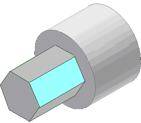
- Right-click the feature you want to drag, and click 3D Grips.
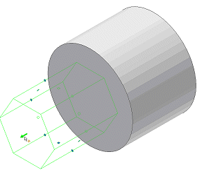
- Click an arrow, and drag toward the opposite face of the base feature.
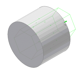
- Drag to the appropriate length.
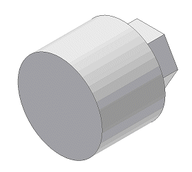
- To quit, right-click, and click Done.
Note: You cannot change the extent type of a feature using 3D grips. For example, you cannot change an extrusion from a join to a cut, or from a cut to a join.
Infer and Create Constraints in Sketched Features
Settings in Application Options, Part tab, control the behavior of constraints.
The inferred constraint (Tangent, Concentric, Coincident, or collinear) depends on the selected handle and the geometry to which it snaps.
Handles visible when grip editing:
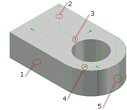
- Sketch Line
- Sketch Point
- Feature
- Sketch Circle
- Sketch Arc
You can infer constraints from a static handle (one that is not dragged) or a dragged handle.
- Click the handle, and then select the geometry to which the feature is constrained.
Inferred constraints preview on the cursor, based on the geometry that projects from the selection.
- To prevent inference of constraints between a static handle and reference geometry, hold down CTRL during selection.
- To prevent inference of constraints between a dragged handle and reference geometry, hold down CTRL while you drag the 3D Grip handle.
- To quit, right-click and select Done. To enter precise coordinates for one or more axes, click Commit And Move.
