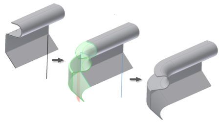
Create a contour roll feature by revolving a profile consisting of lines, arcs, splines, and elliptical arcs.

What's New: 2018
A contour roll feature can be the base feature or a subsequent feature in your sheet metal part model.
To aid in the preparation of detail drawings, Contour Roll centerlines have a unique Object Type and are placed on a separate layer of the drawing.
The following image shows two examples of simple legacy rolls.

In releases prior to Inventor 2015, you can create simple cylindrical or conical rolls. When migrated to the current release, these types of rolls are not converted to Contour Roll features. They retain the attributes and behavior of previous releases.
Create a Contour Roll in Sheet Metal
You can create a contour roll as a regular or a base feature.
The Contour Roll feature lets you create a contour roll as a regular or a base feature. Like the Contour Flange feature, the Contour Roll feature transforms sharp sketch corners into bends in the finished part using the bend radius value.
- Rotation axis geometry must be contained within the sketch containing the profile geometry.
- You can use a Rolled Angle value of 360 degrees only for profiles with a single, straight line. The angle value cannot equal 360 degrees for multi-segment profiles.
- Specifying an alternative Unroll Methods can require more graphical selections or value entries.
- Do one of the following:
- Create or share a sketch consisting of lines, arcs, splines, and elliptical arcs (as required) within your model.
- For a base feature, create a profile sketch consisting of lines, arcs, splines, and elliptical arcs (as required). Include a line to represent the axis of rotation in your sketch or ensure that your sketch is positioned to use one of the default axes as the rotation axis.
- Exit sketch.
- On the ribbon, click
Sheet Metal tab
 Create panel
 Contour Roll
 .
.
- Select the Profile.
- In the Contour Roll dialog box, click the axis selection command and then click the axis of rotation.
- If there are multiple bodies in the part file, click the Solids selector to choose the participating body.
- If necessary, change the direction of the material offset from the profile curve.
- (Optional) If a body exists, click New Solid to create a new body.
- (Optional) Do one of the following:
- Select the Follow Defaults checkbox to link the material thickness and rules to the Default setting.
- Clear the Follow Defaults checkbox and click the drop-list to specify a unique material thickness and rules from the predefined list.
- (Optional) Select an alternative Unroll Method, an alternative Unfold Rule, or an alternative Bend Radius value.
Create Mirror and Pattern Contour Roll Feature
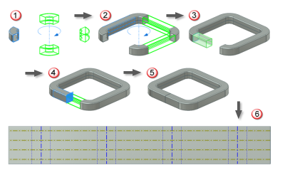
You can create a mirror or pattern feature from a contour roll, as this illustration shows:

- Pattern a contour roll feature in a radial pattern with four total occurrences.
- Add a straight contour flange segment to the model and create a radial pattern with three total occurrences.
- Add a short, straight contour flange segment. This segment does not reach the mid-plane which passes through the radial pattern axis.
- Mirror the short contour flange segment, which joins the exposed detail face of the final occurrence of the original contour roll pattern element.
A mirror operation leaves a gap between the two short contour flange segments.
- Optionally, unfold and flatten the entire model.
Add Unfold Feature to Contour Roll
You can apply two Unfold features to flatten faces of a contour roll feature and continue modeling on the unrolled and unfolded model. Any features that you apply across the bends are deformed when two Refold features are applied and the model returns to the original rolled shape.
Adding an unfold feature to continue modeling differs from generating a flat pattern for fabrication.
- On the ribbon, click
Sheet Metal tab
 Modify panel
 Unfold.
- Select a stationary reference at either end of the contour roll feature.
- Select the contour roll.
- Click Apply.
- Select a stationary reference on the now straightened section to begin the application of the second Unfold.
- Select the bends to unfold.
- Click OK.