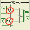
How to display regions of interest in a component view and break (not display) the view in regions without significant details.
You can break a view when the component view exceeds the length of the drawing, and scaling the component view to fit the drawing makes the component view prohibitively small.
You can also break the view when the component view contains large areas of nondescript geometry. For example, you may have to annotate both ends of a shaft, but the center portion of the shaft is free of features. View breaks can be used anywhere along the length of the component. You can also use multiple breaks in a single drawing view.
Dimension lines that pass through a view break, where both points reside outside the area removed by the break, are modified with a break symbol to match the view break lines. Dimensions that pass through a break, where one or both points reside in the area removed by the break, are hidden from display.
- Part view
- Assembly view (not available in Inventor LT)
- Projected view
- Isometric view
- Section view
- Detail view
- Slice operation
Inheritance of the Break
- You can propagate the break operation to the parent view. When you create a break, select the Propagate to parent view option.
- For orthographic projection, breaks are inherited by a child view by default if the view projection direction is parallel to break lines.
- The break inheritance is also supported for child isometric projected views, but breaks are not inherited by default.
Break a Drawing View
The Break dialog lets you specify a break.( Display settings change to match the break style you choose.) For Structural break, you can also use one, two, or three symbols per break.
The Propagate to parent view option controls whether the break operation is propagated to the parent view. The availability of this option depends on type of the view and on the status of the Break Inheritance option.
- On the ribbon, clickPlace Views tab
 Modify panel
 Break(
 ), and then select the view to be broken.
- Specify options in the Break dialog:
- Style. Sets the break style. Rectangular (
 ) creates a break for noncylindrical objects and all sectioned broken views. Structural (
 ) creates a break using stylized break lines.
- Orientation. Sets break orientation to horizontal, vertical, or aligned to the view projection. Horizontal (
 ) sets break orientation to horizontal. Vertical (
 ) sets break orientation to vertical.
- Display. Controls appearance of each break type and works in conjunction with the Style commands. Select a Style command to make its Display settings active.
- Gap. Specifies the distance between the breaks in the broken view. This uses the units specified for the drawing.
- Symbol (
 ). Specifies the number of break symbols for the selected break, and allows up to 3 symbols for each break. (This shows two symbols that the Symbols option sets.)
- (Optional) Select the Propagate to parent view option to propagate the break operation to the parent view.
- Min. - Max. slider. Sets quantity or amplitude of break edge. With the Rectangular command selected, controls quantity or pitch of break edges. With the Structural command selected, controls amplitude of break line. Expressed as a percentage of the break gap.
- Style. Sets the break style. Rectangular (
- Click the drawing view to place the first break line.
- Click the drawing view to place the second break line.
 Show Me How to Create a Broken View
Edit the Break Style, Display, Gap, or Number of a Symbols
You can edit the break style, display, gap, or number of a break line symbols.
However, you cannot edit the break orientation. To change break orientation, you must delete the break, and then place the break again with the new orientation.
- In the graphics window, select a break line, right-click, and then select Edit Break.
- Change any of the options in the dialog.
Edit the Position and the Amount of Component View Consumed by the Break
- Select a view break to highlight the break lines.
- Drag the break lines to change the position of the break.
- Drag either of the break lines to increase or decrease the amount of component view consumed. Moving a break line away from the original view break location increases the amount of component view consumed. Moving a break line towards the original view break location decreases the amount of component view consumed.
Edit the Position and Visibility of a Dimension Line Break
- Select a broken dimension line.
- Do the following:
- To edit the position, drag the broken dimension line break manipulator to the appropriate position.
- To edit the visibility, drag the broken dimension line break so that dimension text hides the break, or drag dimension text to cover the break.
Edit the Visibility of Annotation Symbols Hidden by a View Break
An annotation symbol attached to the area removed by a break is hidden.
- Select the view break.
- Do any of the following:
- Drag the break position or decrease the amount of break consumed to reveal the annotation symbol.
- Change the position of the annotation symbol.