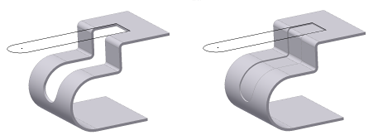
You can specify normal cuts or cuts across a bend. You can also project unfolded geometry in your sketch.
For convenience, you can also project the unfolded geometry in your sketch.
Unfold Sketch Geometry for Cut Feature
When creating a profile sketch to use for a cut feature that cuts across bends, it is useful to have unfolded geometry projected in your sketch. This command projects the flattened face along with bend lines, which you can use to dimension your sketch.
- Select a planar face to start your sketch.
- Use Project Flat Pattern (located with the Project Geometry and Project Cut Edges commands) to select faces next to your originally selected sketch face.
- Use the sketch Slice Graphics option to remove folded model geometry from the plane of your sketch.
Apply Cuts on Sheet Metal Faces
- On the ribbon, click Sheet Metal tab
 Modify panel
  Cut
Cut  .
. - If there are multiple profiles, click Profile and then select the profile for the cut.
- If there are multiple bodies in the part file, click the Solids selector to choose the participating body.
- Select Cut Normal or Cut Across Bend.
- If you selected Cut Normal, under Extents, click a method to terminate the extrusion:
- Distance. Establishes the depth and direction of the cut. The default method is to create the cut perpendicular to the sketch plane. On the Thickness drop-down list, click the method to determine the thickness. Click a direction for the cut.
- To Next. Specifies that the cut terminates on the next plane or face. Click a direction to specify the direction for the cut.
- To. Specifies an ending face to terminate the cut. (You can terminate the cut on a face that extends beyond the termination plane.) In an assembly, the face or plane can be on another part. Click the face on which to terminate the cut. Specify whether the cut extends beyond the selected face.
- From To. Selects beginning and ending faces or planes on which to terminate the extrusion. In an assembly, the faces or planes can be on other parts. To Click the beginning and ending faces for the cut.
- All. Extrudes the profile through all features and sketches in the specified direction. Select the direction of the cut or extrude the cut equally in both directions.
- Do one of the following to specify thickness:
- Accept the Thickness parameter of the sheet metal material as the cut depth for through cuts.
- Specify a partial depth cut as a percentage of the Thickness parameter or enter a precise depth value. Note: Thickness/"n" lets you use a partial depth cut by using the Thickness parameter in an equation. You can specify an absolute depth value. The example on the left shows a simple cut across multiple bends with the distance value set equal to the Thickness parameter. The example on the right shows the same cut with the distance set to Thickness/2.

- Measure. Uses the distance defined by two points or an edge for the thickness of the cut.
- Show Dimensions. Displays the dimensions for a selected feature. Uses the distance determined by a selected dimension as the thickness for the cut.
- List Parameters. Displays a list of the defined parameters in the file. You can select one as the thickness for the cut.
- Specify an offset.
 . Flips the direction of the cut from the default setting. Useful when the cut sketch is created on a reference plane. When the sketch is created on a sheet metal face, results in no material removal.
  . Removes material from the plane of the selected sketch towards the material thickness of the part. Default direction.
  . Defines the cut sketch as the midplane of the cut thickness. Useful when the cut sketch is created on an appropriately positioned reference plane.
 Show Me how to create a cut across a bend
Select a Profile to Remove Material
- Click Profile, and then select Single Profile or Multiple Profiles:
- Single profile. Automatically selects profile, and previews the cut.
- Multiple profiles. Lets you position the cursor over the profile and click to select.
- Click one or more profiles.