Assembly Constraints
When placing a mate constraint between 2 axes, Inventor now predicts the best match based on the selection with minimal rotation. Inventor assigns the optimal selection before displaying the preview.
For example, if you select axis 1 with a direction and then select axis 2, the relative position with minimum rotation is maintained. Also, the type of direction (opposed or aligned) is specified. This behavior allows you to add a manual control to prevent the components from orienting incorrectly.
For more information on placing constraints between 2 axis, see To Place Mate or Flush Constraints in Assemblies.
Express Mode
- Drive Constraint
- Create and edit 2D sketches
- Work feature selection and visibility controls
- Visibility for Shared and unconsumed sketches
- Selection Priority: Select Sketch Features
The following commands are now available in Express mode:
For more information, see About Express Mode and Skeletal Modeling in Express Mode
Assembly Sketch
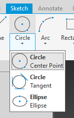
The Ellipse command is moved to the Circle group in the Create panel to provide consistent access in both Part and Assembly environments.
Productivity Tools
Tube & Pipe
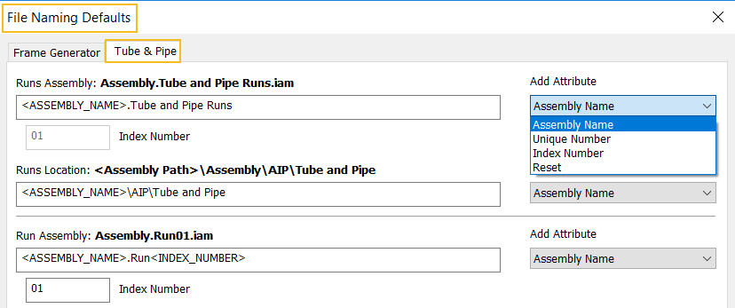
The Application Options  File tab File Naming Defaults dialog box now includes a Tube & Pipe tab where you can specify how Tube & Pipe creates files and folders. For example, you can use these settings to keep the folder structure flat and completely eliminate the AIP sub-directory. In addition, you can now configure the naming scheme using the options in the new Add Attribute drop-list.

For more information, see To Customize the Tube & Pipe Folder Structure.
Design Accelerator/Shaft Generator
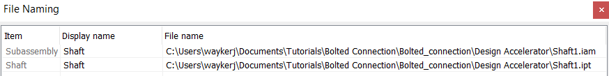
The Shaft Component Generator dialog box now includes a toggle that allows you specify how files and folders for Shaft components are created.
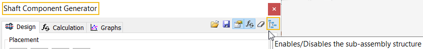
By default, the toggle
 disables the creation of a sub-assembly structure and creates a single part within your root assembly.
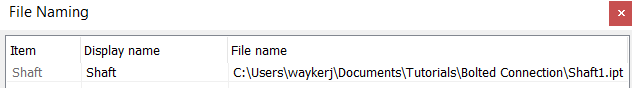
Click the toggle to enable the creation of a sub-assembly
 .
.
For more information, see To Design a Shaft Using Functional Input.
Joint Creation Enhancement
You can now select the center point of a slot to define a joint.
For more information on creating joints, see To Define and Manage Joint Relationships.
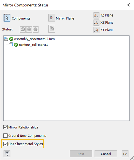
Mirror Components/Sheet Metal Enhancement
The Mirror component command now recognizes a sheet metal part and lets you link the sheet metal style of the source component to the mirrored copy.
For more information, see Mirror Components.
Support for Threads in Assemblies
You can now create thread features in assemblies.
Access:
- Assembly: 3D Model tab Modify Assembly panel Thread

- Weldment assembly: Weld tab Preparation and Machining panel Thread
For more information, see To Create Threads.