Unwrap one or more contiguous faces.
Use this command to unwrap faces that cannot be flattened with the Unfold or sheet metal flat pattern command. For example, fabric or stamped objects. Unwrap does not use bend calculations to flatten the selected faces.
Unwrap part faces
- On the ribbon in a part file
 : 3D Model tab
  Create panel Unwrap.
- Click the Advanced Settings Menu and enable Create Dedicated View Representation to create a view that displays only the flattened surface. The view representation is useful to isolate the surface in a part file, or to document the surface in a drawing.
- If desired, specify a preset.
Note: To specify preferences for Unwrap behavior, click the gear icon.
- Faces: In the graphics window, select one or more contiguous faces.
- Auto Face Chain: Enable to select multiple faces with one pick.
- Position at Origin:
- Enabled: Places the unwrapped surface at the closest vertex of the first selected face. Pick Clear Selections and then pick a new Origin vertex if desired.
- Disabled: Places the unwrapped surface at the XYZ origin of the world coordinate system. If disabled, you can use manipulators in the display to orient and position the output surface.
- Suppress the gusset and create a flat pattern to view the part shape with zero distortion.
- Use Unwrap and select the gusset faces to flatten the gusset with some distortion.
- Optionally, do one of the following:
- Linear Result: Enable to select one or more contiguous edges to remain straight.
- Rigid Result: Enable to select one or more contiguous edges to remain rigid. For example, select a circular edge to maintain a circular shape when unwrapped.
- Merge Result Body: Enable to create the output as a single surface face. Disable to create a single surface with multiple faces.
- To create the unwrap and begin a new unwrap, click the plus sign
 .
.
- Click OK to create the unwrap and finish the command.
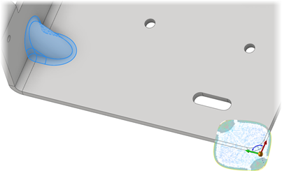
In the following image, Auto Face Chain and Position at Origin are both off, and a stiffening gusset is selected in a sheet metal part.
In this example:
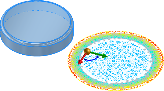
Note: The surface preview displays a surface mesh and heat map. The heat map shows areas of low deformation and tension as blue and areas of high deformation and tension as red. After creation, edit the unwrap feature to view the heat map.
To edit an Unwrap feature:
- Locate the feature in the browser.
- Right-click, select Edit Feature.
- Use the selections in the property panel to make the desired modifications.
- Click OK to accept your changes.
Detail unwrapped surfaces in a drawing
Tip: In the part file, enable the option Create Dedicated View Representation. Use this view representation in a drawing to detail the unwrapped surface.
- In a drawing, start the Base view command.
- In the Drawing View dialog, specify the View representation that shows the unwrapped surface .
- Click OK to create the view.
- Add annotations as required.
Note: Before you create the view, use the View Cube as required to change to a normal view of the surface. If you create a view that is looking at the surface edge, it appears to be empty when created.