The Transform Offset Parent Matrix widget in the Attribute Editor is the first input to let you put a matrix into a node and lets you edit them. You can also view and edit, in a separate tab, its composition.
A Matrix is a 4 x 4 array of floats that represent the translation, rotation, scale, and sheer of a transform node. It gets inserted between its parent and local calculation, so that if you move the parent, the child is moved.
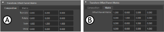
The Transform Parent Matrix tabs in the Attribute Editor A. Composition B. Matrix
Right-click any editable field in the widget lets you set the matrix to Identity or to invert it.
Note: An
Identity Matrix is a neutral matrix that represents the World, or center of you scene. It contains 16 values: value of 1 on the diagonals, but with everything (translation, rotation, and scaling) set to 0 so it decomposes to a translation, rotation of 0, with a scale of 1 and a shear of 0.
- Composition tab
- Modify the Scale, Translate, Rotate, Shear component.
- Matrix tab
- Modify the Scale, Translate, Rotate, Shear component.
Matrix operation nodes
You can chain matrix operations together, similar to how deformation chains work on geometry.
- blendMatrix
- Chain deformations together with the blendMatrix node, where the weight value lets you extrapolate and interpolate.
-
blendMatrix is not a weighted average, but an ordered blend, where each successive matrix overrides the preceding matrices. For example, where a
weighted blend for three matrices might use a value of 1, 1, and 1 for a 50% blend, you will need a weight of 1, .5, and .3333 (or more clearly 1/1, 1/2, 1/3) to achieve the same result with an
ordered blend.
The blendMatrix node has the following options
-
Use Matrix: Activates the blendMatrix node
-
Use Scale/Translate/Rotate/Shear: lets you choose which component (Scale/Translate/Rotate/Shear) will use in the blend calculation.
-
- pickMatrix
- Lets you choose which components from the output matrix to use in the input matrix, for example, you can choose only translation and rotation. Unused components are set to identity.
- aimMatrix
- A hybrid aim/align operation. You can set a transform's orientation by defining a primary and secondary axis. This node lets you set a primary axis through either an alignment or an aim operation that is independent of the secondary axis's aim or alignment operation.
The aimMatrix node has the following options
- Input axis: the axis to be aimed/aligned
-
Mode: the
aimMatrix node has 5 modes:
Mode Function Lock Axis Keeps the input axis from being changed. Aim Aims the input axis at the point defined by the Target vector in the Target matrix. Align Aligns the input axis with the vector defined by the target vector in the Target matrix. None Does not include the secondary axis in the solve. The primary axis takes the shortest quaternion slerp to its solution. Target Vector - Aim mode: the Target vector is treated like a 3D point in the Target matrix.
- Align mode: the Target vector is treated like a vector in the Target matrix. In this mode, you must specify a valid (0,0,0 is not valid).
- pin nodes
- Use these nodes to drive transforms directly by their matrix output. There is also a new pin node UI for creating and editing setups.