Investigate distortion in an additive manufacturing (AM) geometry.
This video discusses the process of importing geometry, selecting a PRM file, solving the simulation, and importing results for analysis.
Video length (6:34).
Follow the step-by-step instructions shown in the video. Sample files for use with the tutorials are available on the Download Page.
- Click .
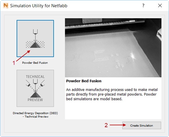
- In the dialog that opens, click
Powder Bed Fusion and then
Create Simulation.
- In the Import Model dialog, browse to and open the sample file Example_3.stl.
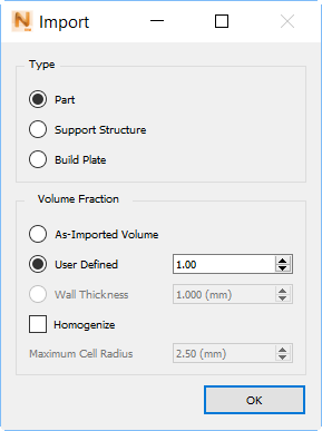
- In the
Import dialog, click
Part, and
OK.
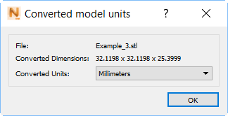
- In the
Converted model units dialog, ensure that
Converted Units are
Millimeters and then click OK.
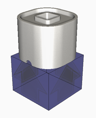
This imports the STL file and automatically sizes the build plate:
Some useful controls for orienting the model are as follows:
- Scroll the mouse wheel to zoom in or out.
- Hold down the right mouse button to orbit freely.
- Hold down the scroll wheel or middle mouse button to move the part without changing orientation.
- Click the View Cube to set a specific view.
- To adjust the build plate size, click
 .
.
- On the
Size tab, adjust the size of the build plate, using the handles for X, Y, and Z axes, or the numeric
Length settings in the dialog box.
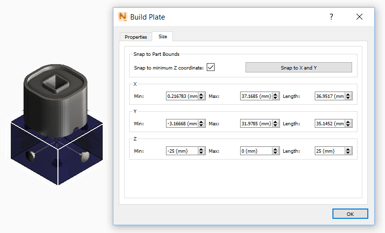
- Once finished, click OK to save the build plate changes.
- Click
to open the
Machine dialog.
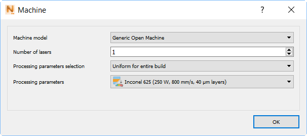
- Leave the Machine Model setting at the default Generic Open Machine.
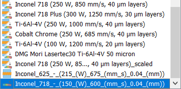
- In
Processing Parameters, select the PRM file you generated in Tutorial 2, or another one for Inconel 718.
- Click
.
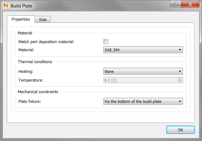
On the Properties tab, deselect Match Part Deposition Material, and in the Material menu, select SAE 304, a stainless steel, which is commonly used with Inconel powder.
- Click OK.
- Before attempting a full simulation, check the quality of the mesh by clicking
Mesh Preview
 .
.
If you have not already saved your project, you will be asked to do so. Choose a file path that will be easy to find later. After a brief wait, the finished mesh appears.

- Click
Solve
 to run the simulation on your computer:
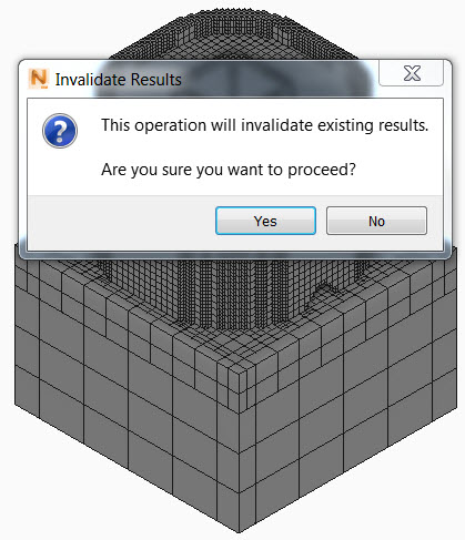
- Click Yes to invalidate (update) existing mesh results.
 Three options are available to check progress of the simulation:
- A progress bar appears in the bottom right corner of the
Simulation Utility view window:

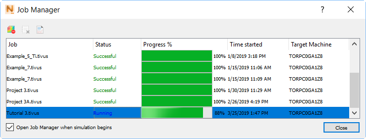
- The
Job Manager
 dialog opens as the simulation starts.
It shows some useful details about the job, including Progress %, Time started, and the Target Machine or computer that ran the job.
- For a deeper look into the progress, click the
logs icon
 in the upper left of the dialog, or the
View Logs icon on the
Home tab.
in the upper left of the dialog, or the
View Logs icon on the
Home tab.
A window opens to show the solver output files in real time. Three tabs at the top, Thermal, Mechanical, and Recoater Blade Interference, report on different aspects of the simulation.
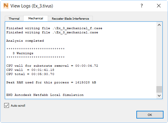
This log displays simulation status details, including the current layer group being solved, the total number of layers to be solved, number of nodes, elements, and equations for each increment, increment number, time, iterations per increment and their associated residuals.
Any warnings or errors during the simulation are displayed in this window. The end of each simulation phase log states the following details:
- "Analysis complete" message
- Total warnings recorded (if applicable)
- CPU wall time, which is the actual time required to finish the simulation
- CPU total time, which would be the time required to finish the simulation for an equivalent single core machine
It's a good practice to examine the logs at the end of every thermo-mechanical simulation; not only will they inform you about errors in the simulation, but if serious build failure mechanisms occur such as recoater blade interference or support structure failure, these will be recorded in the mechanical log file. These topics are explained in more detail in later examples.
- A progress bar appears in the bottom right corner of the
Simulation Utility view window:
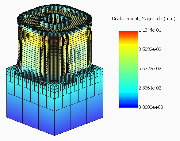
- When the simulation finishes, the results open in Simulation Utility, and the Results tab opens.
- In the Browser on the left side of the window, hide the
Geometry and
Build plate display by clicking the light bulbs next to them so they go from on (
 ) to off (
 ). Turn on the light bulb for
Displacement results.
). Turn on the light bulb for
Displacement results.
- Play through the results using the
Play button
 or other
Animation controls, stopping on the final increment of the simulation.
or other
Animation controls, stopping on the final increment of the simulation.
By default, the legend normalizes to the current minimum and maximum result. You can click inside the legend rectangle to move or resize it. To change the legend to a horizontal or vertical bar, click and drag it out the right side or top of the window, then back in.
- To make the displacement results more visible, click
Plot Settings
 .
.
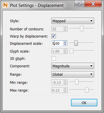
- In the
Displacement scale box, change the value to
5, then click
OK. This warps the part by the predicted displacement and magnifies the effect 5 times, which makes it easier to observe the changes in geometry caused by thermally induced plastic distortion.