Prepare a geometry that is intended to distort into the desired shape.
Video length (2:54).
Sample files for use with the tutorials are available on the Download Page.
In this tutorial, we use the
Warped STL feature to modify the geometry of an STL file to compensate for the distortion that was revealed in a simulation of the original geometry. The figure below illustrates this concept: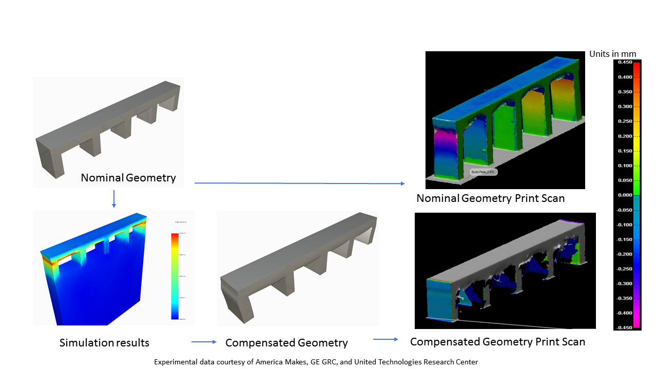
When the nominal geometry is printed, it shows excessive distortion. The same distortion is predicted by the model. Using compensation, the original geometry is altered based upon the predicted displacements, which when printed, shows a significant reduction in distortion.
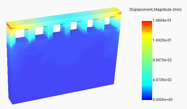
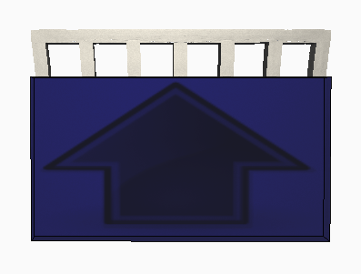
Original displacement results
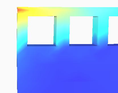
The figure shows simulation results using the file Example_12.stl. Note the areas of maximum displacement at the upper, outer corners of the original part. A closer look shows that these outer corners are displaced slightly inward, toward the center of the part.
When we prepare a compensated STL, we can expect to see the geometry offset in these corners so that displacement during the build will modify the geometry into the desired final shape.
- Open the file
Example_12.tivus in
Simulation Utility, check that the light bulbs for
Geometry and
Build plate are turned off, then turn on the lightbulb for
Displacement results. On the
Results tab, click
Warped STL
 . The
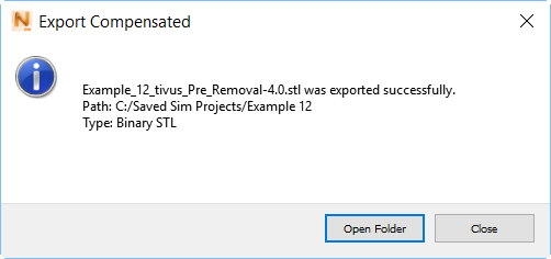
Export Compensated dialog opens.
. The
Export Compensated dialog opens.
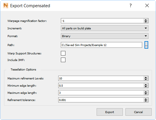
A positive value of 1 in the Warpage Magnification Factor field would export an STL file showing the predicted displacements. A value of -1 would produce a completely compensated STL, applying the full simulated displacements to the original STL dimensions. Values exceeding +/- 1 would produce an STL file with exaggerated displacements or compensation.
- In the Warpage Magnification Factor field, set a high negative value of -4, so the warping will be more visible in the results.
- Check that the STL export path is suitable, redirecting it if necessary, and then click
Export.
The Export Compensated dialog shows you the name of the warped STL file, which contains the warpage magnification factor in an extension of _warp-4.stl, and the path to the file.
- In the dialog, click Open Folder.
- In Simulation Utility, on the Home tab, click Import, browse to the warped STL file and open it.
- In the Browser, check the light bulbs for the Results, and turn off any that are on. Leave on the bulbs for the Geometry.
You should notice that the upper corners are pushed outward to compensate for the expected inward displacement. The warpage magnification factor of -4 was intended to show displacement that is clearly visible, but it is too extreme to use in practice.