Exercise more control over the size and shape of a build plate.
Video length (3:37).
Sample files for use with the tutorials are available on the Download Page.
In this exercise, we will import a build plate STL file and use it to run a simulation.
- In
Simulation Utility, create a new simulation, browse to your saved Examples folder, and from the Example_24 folder, import
buildplate_thin.stl.
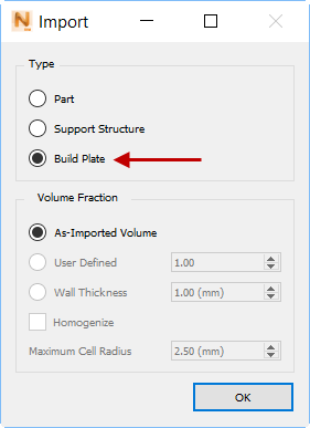
- In the Import dialog, under Type, click Build Plate, and leave Volume Fraction at As-Imported Volume.
- Import Canon.stl from the same folder, but in the Import dialog, click Part for the type, and leave Volume Fraction at the default setting of User Defined.
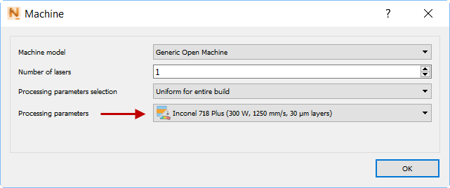
- On the Home tab, click
Machine, and set
Processing parameters to
Inconel 718 Plus.
- On the Home tab, click Build Plate. Notice that the Size tab is not presented here, because you are using a custom build plate of fixed size.
- In the dialog, on the
Properties tab, deselect
Match part deposition material and set the Material to
SAE 304.
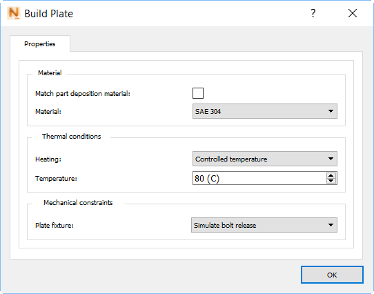
Also, set Heating to Controlled temperature, set Temperature to 80° C, and set Plate fixture to Simulate bolt release.
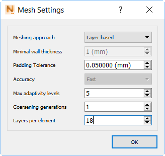
- On the Home tab, click
Mesh Settings, then set Meshing approach to
Layer based, Coarsening generations to
1, and Layers per element to
18, as shown below.
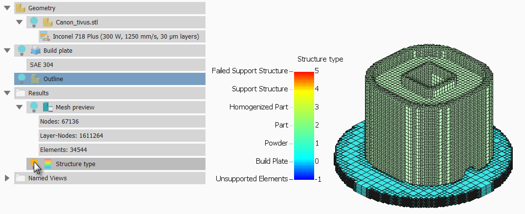
- Click
Mesh Preview, and save the project with a suitable name and location.
When the mesh is displayed, you can check it for errors. In the Browser results, click the lightbulb for Structure type to see the color-coded types before the simulation.
- On the Home tab, click Solve to run the simulation.
Tip: When results are available, to see the display more clearly, right-click one of the Browser result types, select Render Properties, and deselect Element Edges.
- Display
Displacement results, then on the Results tab, click
Plot Settings and set the Displacement scale to
5.00.
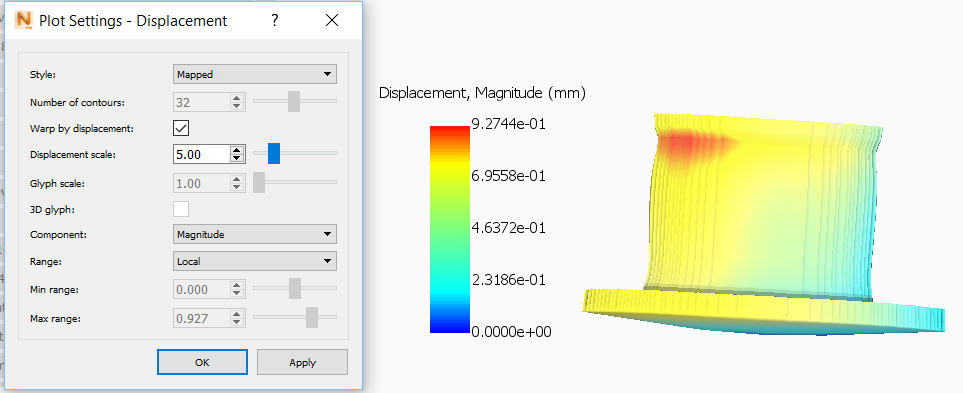
With displacement results exaggerated in this way, you should be able to see quite clearly that the thin build plate has distorted during the simulation.