Draw a polygonal shape on the display and project it through the part as a stencil
There are three types of polygonal shapes you can use as a stencil:
- A free shape where you draw the contours yourself
- A circle (circular polyline contour)
- A rectangular polyline contour
Polygon cuts are projected through the depth of the part based on the current view perspective. Rotate the model after the stencil is created to see its projection.
To create a polygon cut with a free shape
- From the main menu,
Modify >
 Cut > Free Cut.
- In the context view, switch to the
Polygon tab.
Tip: If you just click Modify > Cut, this is selected immediately.
- Click
 Create Polygon.
- Click points on the display to set the corner points for the cutting stencil. As soon as you have set the third point, the stencil is created, and subsequent points are added between the nearest two existing corner points.
- Set further options as required:
- On the Borders tab, enable Add Tolerance Spacing to add some offset to the cutting line which can help reassembling the part later while still maintaining the correct measurements.
- Choose between Inside, Outside, or Both Sides for the offset location.
- Enter a value for the tolerance spacing between the offset line and the original line.
- Enable the Create Round Corners check box to round eligible corners of the cutting. Using the slider you can quickly set up a corner radius between 0 and 10 mm. Using the input field you can specify radii beyond 10 mm. A corner is eligible if the resulting center point of the specified radius doesn't come to lie too far away from the associated corner point, otherwise no rounding is applied.
- Click Cut to complete the cut.
You can save and load existing cutting stencils on the Load/Save tab to reuse the same geometry.
To configure a free-cut edge
The edges of free cuts can be configured to create dove tail, jagged, or puzzle shaped edges.
- Once you have created the free-cut stencil, click
 Edit Edge.
- In the opening dialog, configure variant and shape.
- Select the Count radio button to determine how many edge features are created on each edge or select the Distance radio button to determine the spacing between the edge features.
- Select a Pin Type from the drop-down menu. Available options are: Dove tailed, Jagged, Puzzle
- Edit the dimensions of the selected pin type as required.
- Click Apply to preview and produce the edited edge, and click OK to accept the settings and close the dialog.
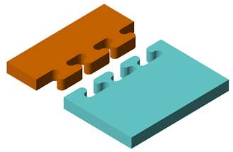
Box cut with puzzle pins
To create a polygon cut with a circle
- Click
Modify > Free Cut.
- Switch to the Polygon tab.
- Click
 Create Circle.
- Click a location in the display to create a circle.
Note: You can drag the center of the circle or click a new point on the part to adjust the positioning of the circle.
- Adjust the radius of the circle as desired using the slider or the input field in the context view.
- Make further adjustments as needed:
- On the Borders tab, enable Add Tolerance Spacing to add some offset to the cutting line which can help reassembling the part later while still maintaining the correct measurements.
- Choose between Inside, Outside, or Both Sides for the offset location.
- Enter a value for the tolerance spacing between the offset line and the original line.
- Click Cut to complete the cut.
To create a polygon cut with a rectangle
- Click
Modify > Free Cut.
- Switch to the Polygon tab.
- Click
 Create Rectangle .
- Click a point in the display to create a rectangle. The center of the rectangle is positioned at this location.
Note: You can drag the center of the rectangle or click a new point on the part to adjust the positioning of the rectangle.
- Make adjustments as required:
- On the Borders tab, enable the
Add Tolerance Spacing check box to add an offset to the cut stencil.
- Adjust the length and width of the circle as desired.
- Click the highlighted corner of the rectangle to rotate the orientation of the rectangle in the stencil.
- On the Borders tab, enable Add Tolerance Spacing to add some offset to the cutting line which can help reassembling the part later while still maintaining the correct measurements.
- Choose between Inside, Outside, or Both Sides for the offset location.
- Enter a value for the tolerance spacing between the offset line and the original line.
- Enable the Create Round Corners check box to round eligible corners of the cutting. Using the slider you can quickly set up a corner radius between 0 and 10 mm. Using the input field you can specify radii beyond 10 mm. A corner is eligible if the resulting center point of the specified radius doesn't come to lie too far away from the associated corner point, otherwise no rounding is applied.
- Click Cut to complete the cut.