In this procedure, you will define the contacts between the links of the chain.
- In the Model tree, right-click .
- In the Surface Contact dialog, set the values below:
- Name: Chain 1-2
- Contact Type: Separation
- Penetration Type: Symmetric Contact
- Stiffness Factor: 0.1
- Coefficient of Friction: 0.2
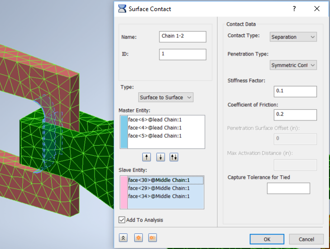
- For Master Entities, select the three inner faces, two curved and one flat, at the back of Lead Chain. For Slave Entities, select the three inner faces two curved and one flat, at the front of Middle Chain.
- Click the
Duplicate button
 , and change
Name to
Chain 2-3. Delete all the Master and Slave Entities.
, and change
Name to
Chain 2-3. Delete all the Master and Slave Entities.
- Create a comparable set of contacts between Middle Chain and End Chain. Master Entities are the three inner faces at the back of Middle Chain, and Slave Entities are the three inner faces at the front of End Chain.
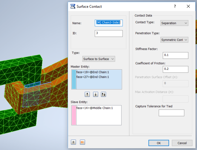
- Click the Duplicate button, delete all the Master and Slave Entities, and name the new contact
Chain3-Side1. For Master Entities, select two faces inside the front of End Chain, the flat left side, and the curved face in front of it. For the Slave Entity, select the contacting flat face on the left side of Middle Chain.
- Press Duplicate, erase entities, and create a similar contact, Chain3-Side2, on the other side of the link between End Chain and Middle Chain. Repeat the process to create contacts for the link between Middle Chain and Lead Chain, Chain2-Side1, and Chain2-Side 2. In each case, there are two Master Entities inside the back link, and one Slave Entity on the outside of the front link.
- Click OK on final Surface Contacts dialog.