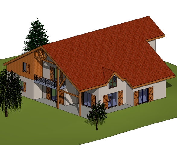
Orthographic 3D views show the building model in a 3D view where all components are the same size regardless of the camera’s distance.
- Open a plan, section, or elevation view.
- Click View tab
 Create panel
 3D View drop-down
 Camera.
- Click Manage tab
 Views panel
 Camera.
- On the Options Bar, clear the Perspective option.
- Click once in the drawing area to place the camera, and click again to place the target point.
An unnamed 3D view of the current project opens and displays in the Project Browser. If an unnamed view already exists in the project, the 3D tool opens the existing view.
You can rename the default 3D view by right-clicking the view name in the Project Browser, and clicking Rename. Named 3D views are saved with the project. When you rename the default, unnamed 3D view, the next time you click the 3D tool, Revit opens a new unnamed view.
You can use a section box to limit the viewable portion of a 3D view.
To place camera above southeast corner of model
- Click View tab
 Create panel
 3D View drop-down
 Default 3D View.
This action places the camera above the southeast corner of the model with the target positioned on the center of the ground floor.

Example