Review these concepts and notions before starting to work with steel connections for Dynamo.
Script Flow
A typical steel connections for Dynamo script starts from a selection of model elements, moves on to grouping those elements into potential connection nodes, filters those nodes based on some criteria, and then places the connections.
Structure Data
- Some internal identification of the framing element - used at a later point to identify the elements that need to be connected.
- The start and end points of the framing element - used to compute slope angle, slant angle, angle between axes. The start and end points of the framing element are also used for the grouping mechanism.
- The section data of the framing element (profile, type, shape) which is also used for filtering.
Framing Element Axis
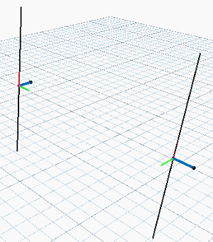
Each Revit structural family has its axes defined. These axes are family-specific, the common thing being that the X axis is always along the length of the framing element.


Indexes
- described using the available filters
- labeled using a zero-based index - the connection is placed based on the indexes
- Open or create a model containing some sample framing elements (column and beam), but no connections.
- Click Steel tab
 Connection panel
 (Connection Settings).
- On the Connections tab, specify the structural connections to load - in this case, the Knee of frame, bolted, with haunch connection.
- Click Steel tab
 Connection panel
 (Connection).
- In the element Properties, select the connection and hover over its type name to reveal the tooltip that shows the number of elements, the selection order and the accepted profiles.
- Create a script that groups into connection nodes of two framing elements, and filters the first element (index 0) to be vertical and of I section, and the second element (index 1) to have the desired slope and to create the connection having as the first input element, the column (index 0) and the second input element, the beam (index 1).
Zones
A single framing element (beam or column) has two ends, and a body between the two ends. Both the body and the ends are called zones. Zones are identified by the grouping mechanism.

- Beam ends
- Beam body
Grouping mechanism
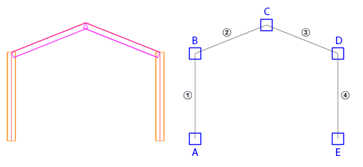
For a given model, a grouping algorithm is used to identify locations where connection nodes could be placed.

 - Column B1
 - Beam B2
 - Beam B3
 - Column B4
A - Node A: Column B1 - End
B - Node B: Column B1 - End; Beam B2 - End
C - Node C: Beam B2 - End; Beam B3 - End
D - Node D: Beam B3 - End; Column B4 - End
E - Node E: Column B4 - End