Create an L-shape or U-shape winder run component by specifying the lower endpoint of the run.
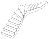
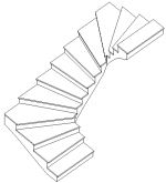
The winder run will automatically connect the base and top elevations. (L-shape winder is used for illustration in this procedure.)
 Video: Create a Winder Stair
To create a winder run
- Select the winder run component tool and specify initial options and properties.
See Selecting the Run Component Tool and Specifying Options.
- On the Options Bar, for Location Line, select either Exterior Support: Left or Exterior Support: Right if you are aligning a run with supports to a wall.
For aligning a run without supports, Exterior Support: Left and Run: Left have the same alignment behavior (as do Exterior Support: Right and Run: Right).
- On the Options Bar, clear or select Mirror Preview to change the default winder layout direction.
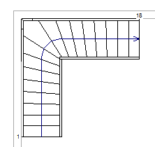
- Press Spacebar to rotate the shape of the winder run so the turn is facing the required direction.
- If positioning the run against a wall or other element, move the cursor near the wall, and notice that the winder stair snaps to position against the wall.
- Click to place the winder run.
- Use the direct manipulation controls to relocate a run leg or balance the steps between the winder legs, as well as to modify other layout properties.
See Modifying Stair Components Using Direct Manipulation Controls.
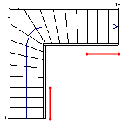
- Optionally, you can replace winder steps at the beginning and end of the run with straight (uniform) steps.
- Select the run.
- On the Properties palette, under Winders, enter the desired number of uniform steps for Parallel Treads at Start and Parallel Treads at End.
In the following image, 3 parallel treads were specified at the start and end of the winder run.
- Optionally, on the Quick Access Toolbar, click
 (Default 3D View).
- On the model panel, click
 (Finish Edit Mode).