Create a 3D shape by sweeping a 2D profile around an axis.
 Video: Create a Revolve
For information about using revolves in families, see Creating Family Geometry.
About revolves
A revolve is a form that you create by revolving a shape around an axis. You can revolve the shape in a circle or any fraction of a circle. If the axis touches the revolve shape, the result is a solid.
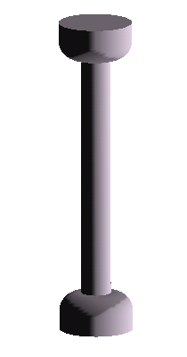
Solid revolved geometry created near axis
If you sketch away from the axis, the resulting geometry has a hole in it.

Revolved geometry created away from axis
Use solid revolves to create family geometry like door and furniture knobs, columns, and dome roofs.
The following procedure is a general method for creating revolved geometry. Steps may vary depending on your design intent.
To create a solid or void revolve
- In the Family Editor, on the Create tab
 Forms panel, do one of the following:
- Click
 (Revolve).
- Click Void Forms drop-down
 (Void Revolve).
Note: If necessary, set the work plane before you sketch the revolve. Click Create tabWork Plane panel (Set).
- Click
- Place an axis of revolution:
- On the Modify | Create Revolve tabDraw panel, click
 (Axis Line).
- Specify the start and endpoint of the axis at the desired orientation.
- On the Modify | Create Revolve tab
- Use the Draw tools to sketch a shape to revolve around the axis:
- Click Modify | Create Revolve tabDraw panel
 (Boundary Line).
- To create a single revolve, sketch a closed loop.
- To create more than one revolve, sketch multiple, non-intersecting, closed loops.
Attention: If the axis touches the revolve shape, the result is a solid. If the axis does not touch the revolve shape, the revolve will have a hole in it. - Click Modify | Create Revolve tab
- On the
Properties palette, change the properties of the revolve:
- To change the start and end points of the geometry to revolve, enter a new Start and End Angle.
- To set the visibility of a solid revolve, under Graphics, for Visibility/Graphics Overrides, click Edit.
- To apply a material to a solid revolve by category, under Materials and Finishes, click in the Material field, and click
 to specify a material.
- To assign a solid revolve to a subcategory, under Identity Data, for Subcategory, select a subcategory.
- Click Apply.
- On the Mode panel, click
 (Finish Edit Mode).
- To view the revolve, open a 3D view.
- To resize the revolve in the 3D view, select and use grips to edit it.
Note: You cannot drag the start and end faces of a 360-degree revolve.