You can map a Revit MEP fabrication part to a specific Autodesk Fabrication product part.
Part mapping is the process of creating an association between an MEP fabrication part defined in Revit as a Revit family, and a similar or corresponding part defined in an Autodesk Fabrication product (CADmep, ESTmep or CAMduct). The Revit MEP fabrication part is based on a Revit family name and type (.rfa file), while the same or similar part in an Autodesk Fabrication product is based on both an .itm file, and a Button Code, which identifies the part when using Design Line.
An .itm file is a file format that typically originated in the Autodesk Fabrication product (CADmep, ESTmep, CAMduct) content and defines a fabrication part.
For example, when you have valve families without fabrication connectors, you can map them to a MEP Fabrication .ITM to enable detailed couplings and accurate pipe lengths.
To map a Revit MEP fabrication part to a corresponding part (.itm) in an Autodesk Fabrication product:
- In Revit, determine the family names of the part(s) you want to map, including the type (size) of the part(s).
This example uses a butterfly valve part with a Revit family name of Butterfly Valve – 2 -12 Inch, and a type of 6”, as shown below in the Type Selector.

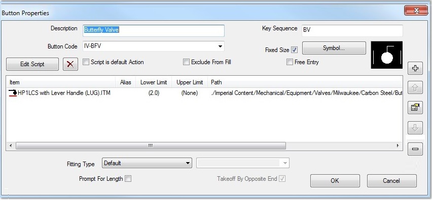
- In an Autodesk Fabrication product, determine the Button Code for the desired corresponding part. In the Service palette, right-click on the part, and click Button Properties.
The Button Properties dialog displays. In the following example, the Button Code for the Butterfly Valve part is IV-BFV.

Next, create the button mapping in the Autodesk Fabrication product. The following steps describe how to do that.
- In an Autodesk Fabrication product, use the folloing steps to create a button mapping for a part:
- Open a job with the configuration containing the part(s) you want to map to.
- Select the desired service, then click Edit Service Database.
- In the Setup Services dialog, select the desired Service in the drop-down.
- Click the Button Mappings tab.
- Optionally, you can create a heading row in the Button Mappings table to organize the Revit Mappings entries:
- Click New Entry.
- In the Define Button Mapping dialog, in the Button Code field, enter the text that you want to use as a heading. For example, enter -------Revit Mappings-------.
You may need to resize this dialog to enter the desired text.
- Leave the Can be Made By Using Alternates field blank, and click OK.
- On the Button Mappings tab, clear the check box next to this entry so that it is not used as a Button Code.
- Click New Entry again.
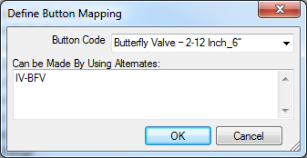
The Define Button Mapping dialog displays.
- In the Button Code field, type in the Revit family name and type of the Revit part that you want to create the mapping for, using an underscore character between the family name and the type, as shown below.

This example uses the Revit Family name of Butterfly Valve – 2-12 Inch and a type of 6”.
Note: Make sure to use an underscore character as a separator between the Revit Family name and type. Also, you may need to resize the Define Button Mapping dialog to enter longer text strings. - In the Can be Made By Using Alternates field, type in the Fabrication Button Code for the corresponding part in the Autodesk Fabrication products.
As noted in Step 2 above, the Button Code for this Butterfly Valve example is IV-BFV.
- Click OK on the Define Button Mapping dialog.
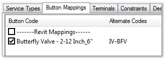
Now the Button Mappings tab entries should look similar to this:

- Click OK to close the Setup Services dialog.
- In Revit, on the Fabrication Part Browser, click the Settings button to open the Fabrication Settings dialog.
- Click Reload Configuration to upload the updated version of the service that contains new button mapping(s), and click OK.
Also note that when using Revit, there may be times that you need to convert a design model with Revit elements to a fabrication model with LOD 400 fabrication parts. For more information on this workflow, see Convert Generic Parts to Fabrication Parts.