Learn how to create new type of member and how to assign it to the selected elements in the structure.
- Continue working in your project or open the project Frame_3D_Results.rtd.
Note: The Tutorial files are located in C:\ProgramData\Autodesk\Examples\Tutorials
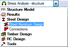
- In the Standard toolbar, expand the Layouts drop-down menu and select Steel/Aluminum Design as shown below:
The layout is divided in three parts: View, Definitions, and Calculations dialogs.
- Click
 (Design
  Steel Members Design - Options Code parameters).
The Member Type dialog opens.
- Select Beam, and then click
 (New steel member type definition).
The Member Definition Parameters dialog opens.
Tip: Select the Member Type that is most similar to the new type that you want to create so that some of the basic properties are automatically applied. - Type Beam_1 in the Member type text box.
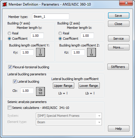
- In the Buckling length coefficient Y group of options, click
 .
.
The Buckling Diagrams dialog opens.
- Click
 , and then click OK.
The buckling effects are removed from the calculations.
- Repeat steps 6 and 7 for the Buckling length coefficient Z.
- In the Lateral buckling parameters group, click
 .
.
The Parameter Cb dialog opens.
- Click
 , and then click OK.
 - Click Upper flange, then in the Lateral buckling length coefficients dialog, click
 (Intermediate bracings).
The Internal bracings dialog opens.
- In the Define segments between bracings group of the Lateral buckling-upper flange tab select Define manually coordinates of the existing bracings, and then type 0.5.
The Bracing is displayed in violet on the view as shown below.
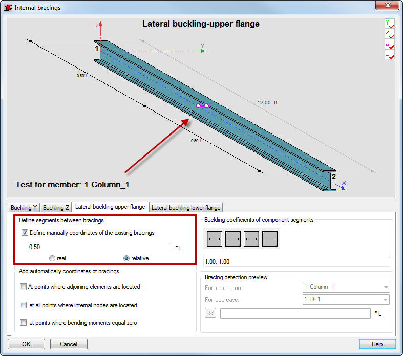
- Go to the Lateral buckling-lower flange tab and repeat step 12 for the lower flange.
- Click OK to close the Internal bracings dialog.
- The information in the Member Definition dialog box should now look like the example shown below.
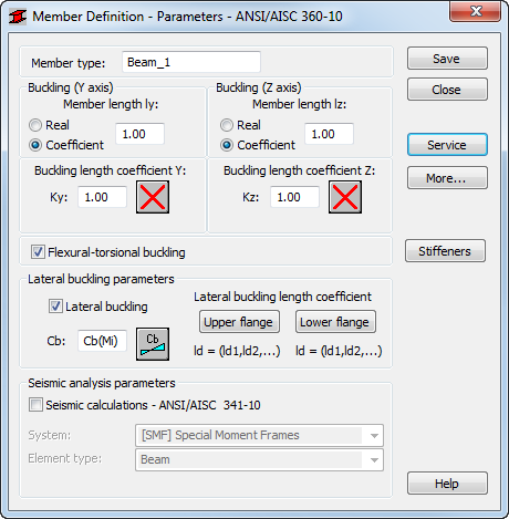
- Click Save, and then click Close.
The new member type is now listed in the Member Type dialog.
- Ensure that Beam_1 is selected in the Member Type dialog, and then type "6 7 11 12" in the Lines/Bars field as shown below.
Alternatively, place the cursor in the Lines/Bars field, then go to the drawing area, and hold the Ctrl key to select beams with numbers 6, 7, 11 and 12.
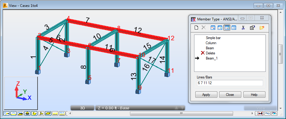
- Click Apply, and then click Close.
- Save the project as Frame_3D_New_Member.rtd.