Learn how to change member types and how to create a new member type.
- In the Definitions dialog box, note that Number 1 is selected and that it is set to the Member type: Simple Bar.
- Expand the Member type drop-down list and select Column. Change the Name to Column_1 as shown below. Click Save.
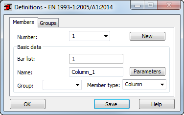
- In the Definitions dialog box, change the Number to 2, Name it Column_2, and change the Member type to Column. Click Save. The beams need to be changed as well, but the standard Beam Member type definition is not appropriate for this situation.
- In the Structure Definition toolbar, click
 (Steel/Aluminum Member Type).
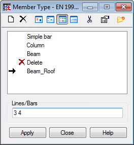
 - In the Member Type dialog box, highlight Beam and click
 (New steel member type definition).
Note: Highlight the Member Type that is most similar to the new type that you want to create so that some of the basic properties are automatically applied.
(New steel member type definition).
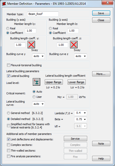
Note: Highlight the Member Type that is most similar to the new type that you want to create so that some of the basic properties are automatically applied. - In the Member Definition dialog box, in the Member type text box, type Beam_Roof.
- In the Lateral buckling parameters area, select Lateral buckling.
- Click Upper flange.
- In the Lateral Buckling Length Coefficient dialog box, click
 (Beam) and set the Lcr to 0.2 lo as shown below. Click OK.
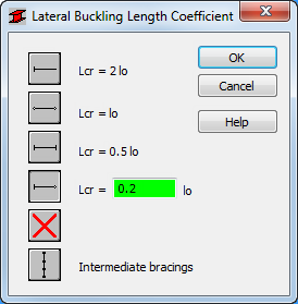
- Repeat this process for Lower flange.
- The information in the Member Definition dialog box should now look like the example shown below. Click Save and then click Close.
- The new Member Type is now listed in the Member Type dialog box. Ensure that it is selected, type 3 4 in the Lines/Bars field as shown below, and click Apply.
- Close the Member Type dialog box.
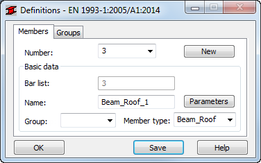
- In the Definitions dialog box, set Number to 3. The Member type is already set to Beam_Roof. Verify that the Name is set to Beam_Roof_1 and click Save.
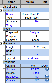
- Change the Name of Member 4 to Beam_Roof_2 if needed, and click Save.
- Save the project.
Note: Another way to check and modify member names and types is by using the Start Layout. Select the bars and then change the properties as shown below.
- Save the project.