Figure 1
Autodesk Inventor has two different types of dimensions - model and drawing. These can be thought of as controlling and documenting, respectively. Model dimensions are typically parametric constraints intended to control part or feature size. Sketch dimensions are included in this category since they directly affect model size and constraints.
Drawing dimensions simply document a given dimension on a drawing sheet, and have no effect on model size or constraints. However, drawing dimensions can be promoted from a draft view to an underlying sketch, or can be retrieved from a sketch or model.
Drawing dimensions are associative, but not parametric. There are various types of drawing dimensions supported, including general, linear, ordinate, radius, diameter, and angular. Options controlling the appearance of dimensions are specified through dimension styles, enabling support of common dimension standards. Individual settings may be overridden to suite.
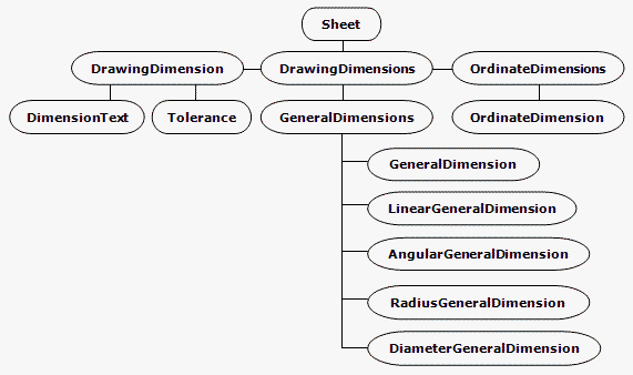
The Drawing Dimensions API provides access to all drawing dimensions on a sheet. Objects corresponding to the available dimension types are derived from a common object named DrawingDimension which contains common methods and properties, such as tolerance, precision, text and so on.
Ordinate dimensions differ from other types in that a given sequence of dimension values will reference the same single point of origin. Figure 1 shows the object model diagram.
Figure 1
Drawing dimension creation methods expect geometry points to be supplied in the form of GeometryIntent objects. To better understand such objects, imagine a leader line and arrow pointing to a user-selected point on a drawing line. Leader line associativity to the selected spot on the drawing line needs to be maintained, but there is no point geometry midway on the drawing line to reference. In this case, a GeometryIntent object encapsulates the intent to reference a location on the drawing line, a certain distance from a particular end.
Similarly, dimensions require GeometryIntent objects because, unlike the Autodesk Inventor modeling environment, the drawing environment contains only 2D lines, arcs and circles - no points. So, a GeometryIntent object for a dimension might reference a particular end of a line or arc, or the center of a circle or arc.
This sample VBA code listing may be cut and pasted into a module in the Autodesk Inventor VBA editor. Make sure all grayed sections are present. Immediately before each grayed section is text describing that section's purpose and operation - do not copy this text into the editor. The code omits error checking for the sake of clarity and brevity. In your code, always check that return values are of the expected type. Ensure that the Autodesk Inventor Object Library is available in your project; in the Visual Basic Editor, pick Tools > References, and check the appropriate reference.
This code creates a simple linear dimension of a curve on a drawing sheet. It assumes the curve is selected before the code is run. Figure 2 shows two lines selected in the sample Vertical Plate.idw.
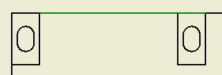
Figure 2
Select the highlighted lines, then run the VBA code. The code first obtains the active sheet from the active document.
Sub CreateDimension()

    Dim oDoc As DrawingDocument
    Set oDoc = ThisApplication.ActiveDocument

    Dim oSheet As Sheet
    Set oSheet = oDoc.ActiveSheet
|
Next, obtain DrawingCurve objects from the selected lines. DrawingCurve objects are acceptable for creation of GeometryIntent objects.
    Dim oCurve1 As DrawingCurve
    Set oCurve1 = oDoc.SelectSet(1).Parent

    Dim oCurve2 As DrawingCurve
    Set oCurve2 = oDoc.SelectSet(2).Parent
|
Now we're ready to create the GeometryIntent objects. Since we're using the DrawingCurve end points, there is no need to specify a point on the geometry, which would be provided by the optional second argument for CreateGeometryIntent.
    Dim oIntent1 As GeometryIntent
    Set oIntent1 = oSheet.CreateGeometryIntent(oCurve1)

    Dim oIntent2 As GeometryIntent
    Set oIntent2 = oSheet.CreateGeometryIntent(oCurve2)
|
Create a 2D point for the location of the dimension line.
    Dim oPt As Point2d
    Set oPt = ThisApplication.TransientGeometry.CreatePoint2d(15, 15)
|
Create a linear dimension on the sheet, using the two GeometryIntent objects as dimension extension line origin points, and the 2D point for the dimension line location.
    Dim oLinDim As LinearGeneralDimension
    Set oLinDim = oSheet.DrawingDimensions.GeneralDimensions.AddLinear(oPt, oIntent1, oIntent2)

End Sub
|
The sample code will produce a result similar to that shown in Figure 3.
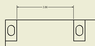
Figure 3