Inventor 2017 R2 includes productivity enhancements voted on by Inventor users worldwide. Over 40 enhancements have been made in sketching, part and assembly modeling, design automation, drawings, interoperability, and presentations to help you get your work done faster and make great products.
General
Improvements to Measure Command Precision
Visual enhancement: A check mark
 now displays next to the default Measure Distance, Angle, Loop, and Area
  Precision value when you access the list for the first time in a file. Previously the check mark only displayed after you made a selection.
The checked
measure precision value now persists across sessions in all files. Select a different measure precision value to change the default measure precision value. Previously when you changed the Precision value in existing files, the change was not maintained after saving, closing, and reopening the file.
For more information, see To Measure Distance, Angle, Loop, or Area in Model.
Enhancements to Projects dialog box (not available in Inventor LT)
- Access to the Configure Library dialog box has been simplified from two clicks to one click. The drop-down button with only one entry has been removed.
- The Inventor project wizard, the wizard that displays when you create a project (.ipj) file, is now resizable.
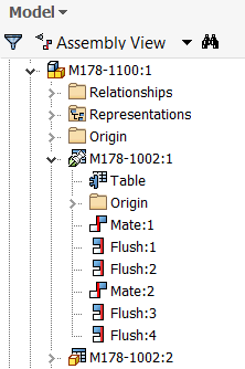
Model Browser Enhancement
The visual display of model browser in all environments now displays lines in the hierarchy to:
- Show a bigger difference between the expanded and collapsed states.
- Help focus attention on content and features.
- Make it easier to navigate the hierarchy.
Workflow Enhancements
- Part/Assembly/Flat pattern sketches now maintain the properties specified in the Geometry Properties dialog box (for example, line type, scale, line color, and line weight) when exported as an AutoCAD DWG file.
- You can elect to display or not display the mini-toolbars when you access one of the following commands: Extrude, Revolve, Fillet, Shell, Face Draft, Chamfer, and Joint. These dialog boxes have a mini-toolbar that displays alongside of the dialog box. The available options on these mini-toolbars are the same as the dialog box options. To maximize the amount of graphical space, use the new View panel User Interface panel
Mini-Toolbar
command to turn off the display of these mini-toolbars.
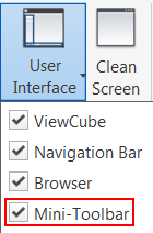
For more information, see Mini-Toolbar.
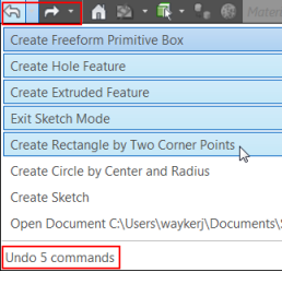
- You can now easily jump back and forth to a different point in time. Your undo/redo history now displays in the new Undo/Redo drop-down menus. Click a drop-down arrow and select from a list of actions you want to undue or redo.

Parts
New Context Menu Options for Make Part and Make Components
From the browser or the graphics window in a part file:
- Make Part: Select one or more sketch blocks, solid bodies, or surface bodies and select Make Part from the context menu.
- Make Components: Select one or more sketch blocks, or one or more solids and select Make Components from the context menu.
For more information on Make Part see, Create Part from Layout.
For more information on Make Components see, Create Components from Layout.
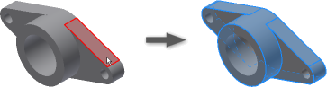
Automate Selection of all Faces or Edges Tangent to the Preselected Faces or Edges
You can now quickly create a selection set of all the faces or edges tangent to each other. In the graphics window:
- With the left mouse button, double-click a face or an edge.
- Select one or more faces or one or more edges, right-click, and select
Select Tangencies from the context menu.
Note: Hold down the CTRL key to select more than one face or edge.
OR
Example selecting tangent faces: Right-click a face, select Select Tangencies OR with the left mouse button, double-click a face. Result: All tangent faces are selected.
Examples of uses
- Use the selection set of tangent faces to:
- Delete the selection set with Delete Faces.
- Assign an appearance to the selection set.
- Add or remove thickness to faces, or create an offset surface from a part face with the Thicken/Offset command.
- Use the selection set of tangent edges to:
- Fillet or chamfer the preselected edges.
- Review or check for tangency conditions or closed loops.
For more information, see Select Command Reference

Enhancements to Revision Tables and Parts Lists Exported Excel Formats
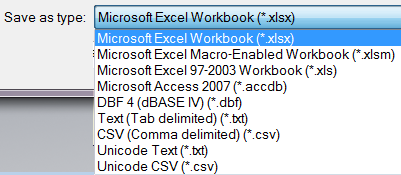
- You can now select an excel template file (.xlsm) with macros when exporting. Macros are maintained in the exported excel file.
For more information on selecting an excel template for export see, Microsoft Excel Export Options Reference
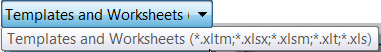
- You can now export Revision Tables and Parts Lists to an excel macro-enabled file (.xlsm). The following excel file types are now supported from a Parts List or Revision table for export: *.xltm;*.xlsx;*.xlsm;*.xlt;*.xls excel templates.
For more information on exporting a Revision Table or Parts List see, Export Parts List, Export Table Reference
Assemblies (not available in Inventor LT)
Mirror and Copy Assembly Options to Include or Exclude Relationships
Previously relationships were automatically applied to the mirrored or copied components. New options let you decide if you want to include the relationships in the operation.
- Mirror Components dialog box: Mirror Relationships If the check box is selected, existing relationships between the source components are applied to the mirrored components. Clear the check box to exclude the relationships.
- Copy Components dialog box: Copy Relationships If the check box is selected, existing relationships between the source components are applied to the copied components. Clear the check box to exclude the relationships.
For more information on assembly mirror, see To Mirror Assembly Components.
For more information on assembly copy, see To Copy Assembly Components.
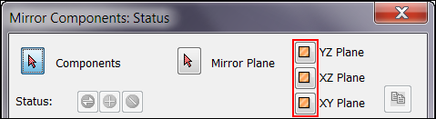
Mirror and Copy Assembly Option to Ground the Resulting Components
The new option Ground New Components in the Mirror Components dialog box/Copy Components dialog box automatically grounds the resulting mirrored or copied components:
For more information on assembly mirror, see To Mirror Assembly Components.
For more information on assembly copy, see To Copy Assembly Components.
Additional Assembly Enhancements
- You can now quickly select from a list of available origin workplanes from the assembly Mirror Components dialog box. Instead of having to locate the workplane and expand the browser node to select it, you can make your selection directly inside the assembly Mirror Components dialog box (not available in Inventor LT).
For more information on assembly mirror, see To Mirror Assembly Components.
- You can now open multiple files from the Bill of Materials. Select one or more components, right-click, and select Open: All selected components open in new separate tabs (not available in Inventor LT).
For more information, see To Work with Bill of Materials.
Interoperability
Quickly Customize Properties for Imported CAD Files with the New Property Mapping Tool
Use the new Property Mapping for Imported CAD Data tool to easily map properties from CATIA, Pro/Engineer and Creo parametric, NX, STEP, and Solidworks to standard Inventor properties.
The new Property Mapping tool replaces the manual effort of directly modifying the CATIA, Pro/Engineer and Creo parametric, NX, STEP, and Solidworks XML design data files.
Public Public Documents Autodesk Inventor [version] Design Data Import Properties.
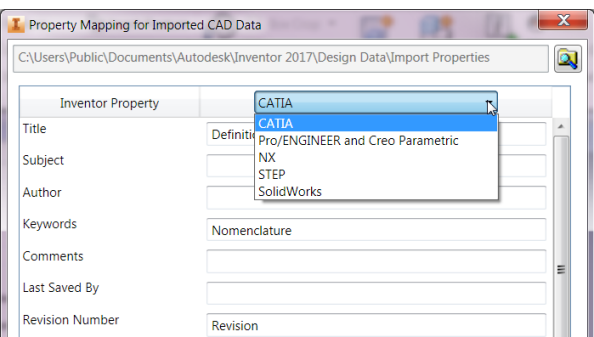
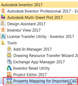
Access the new Property Mapping for Imported CAD Data tool from:
- The Property Mapping button at the bottom of the Import dialog box. This button is only enabled if you are importing a CATIA, Creo, NX, STEP, or Solidworks file into an assembly file.
- Start menu Programs Autodesk Inventor 2017 Tools.
For more information, see To Map Properties from Imported CAD Data to Standard Inventor Properties.
Reference Model Enhancement to the Parts List and Bill of Materials (BOM) (not available in Inventor LT)
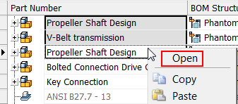
You can now open the top-level assembly of an associative reference or virtual part from a Parts List or BOM. Right-click on a parts list or BOM row that contains an associative reference or virtual part and select Open. The top-level assembly containing the reference to the associative AnyCAD reference or virtual part opens.
For more information, see About Importing Files from other CAD Systems.
DWG Underlay Now Fully Supports AutoCAD Mechanical Geometry
- You can now use the DWG Underlay Locate command to change the insertion point of AutoCAD Mechanical geometry. The relocated geometry maintains the associativity to the AutoCAD Mechanical model.
- Constraints can now be added to DWG Underlay AutoCAD Mechanical geometry in the assembly environment.
For more information on associative DWG, see:
- To Work with Associative DWG in a Part and Assembly File.
- To Create 3D Inventor Models of 2D DWG Underlay Layouts.
Mesh Support for DWF Export
You can now export mesh geometry in DWF format. Open a mesh model such as .stl or .obj and then Export to DWF.
Enhanced BIM content publishing capabilities using Configurator 360
A workflow has been added that helps you prepare Inventor assemblies for use with Configurator 360. The Configurator models can then be accessed and consumed on demand by BIM customers working in the AEC industry.
iLogic (not available in Inventor LT)
iLogic Input Field Enhancement
The iLogic input field in the InputListBox dialog box now automatically resizes to fit the width of the longest input string.
Edit Rule Dialog Box Enhancements
- Use the new option, Save, to save your work as needed during an editing session without running the rule.
- The OK button is replaced by Save & Run: This option saves and runs the new or updated rule and closes the dialog box if successfully run. This option is disabled if the form is suppressed.
For more information, see To Work with Rules in iLogic.
Drawings
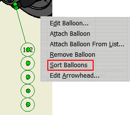
Reorder Attached Balloons with the New Sort Balloons Context Menu Option (not available in Inventor LT)
You can now reorder attached balloons by their value. First, attach balloons using the Attach Balloon From List context menu option. Then, after closing the Attach Balloon dialog box, right-click on the balloon stack and select Sort Balloons. Values are automatically reordered.
- Numeric attached balloons are reordered from smallest to largest.
- Alpha attached balloons are reordered from A to Z.
For more information see, Edit Balloons.
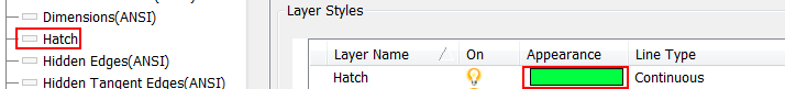
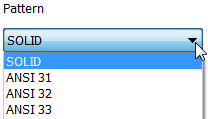
Specify a Hatch Pattern as SOLID
SOLID is added as an available pattern in the Style and Standard Editor dialog box. This option allows you to make the default hatch pattern SOLID for the Hatch style and for the Weld Bead Recovery style.
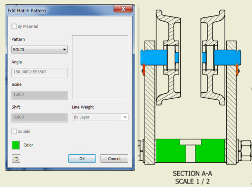
By default the SOLID fill color is black. Change the default color to a color you prefer by changing the Appearance (color) of the Hatch Layer style Hatch object in the Style and Standard Editor dialog box.
You can also manually override the default hatch pattern or default color in the Hatch/Color Fill dialog box.
Example of the SOLID hatch pattern fill in a 2D view.
For more information on adding and editing a Hatch Pattern, see To Add and Edit Hatch/Color Fill to Drawing Sketches.
For general information on creating default styles, see Style and Standard Editor - Object Defaults Style Reference.
Improvements to Deferring Updates on a Drawing
When opening a drawing that is set to defer updates you can now select from the following list and specify your preference for the frequency of being prompted with the message: Drawing updates are deferred. Change defer status to update drawing views and associate added annotations.
- Always show this message.
- Prompt only once per operation.
- Do not show this message again this session.
- Do not show this message again ever.
This defer update message also displays:
- In a tooltip when you hover over the browser status icon of a deferred drawing open in Inventor.
- In a tooltip when you select Defer Updates in the Documents Settings dialog box.
For more information, see To Work with Automatic Drawing Updates.
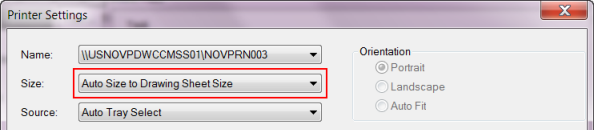
Save Time Printing Multiple Drawings with Auto-Size to Drawing Sheet Size
The new Auto Size to Drawing Sheet Size option in Task Scheduler's Printer Setting dialog box allows you to batch print multiple drawing (.idw/.dwg) files set to different sheet sizes and orientation. This new option automatically chooses the appropriate paper size and orientation as specified in the drawing sheet setting.
This setting is only available when the files in the Task Scheduler Print Files dialog box are drawing (.idw/.dwg) files.
|
---------------Task Summary---------------- This task has processed 1 file(s) out of which 1 file(s) failed. Errors encountered as follows: C:\Users\itools\Desktop\New folder\80-110.dwg--Printer does not support designated paper size, unable to process valid output on accurate sheet size. ------------------------------------------- |
For more information, see To Print with Task Scheduler.
Align Multiple Center Marks in a Drawing to the Selected Edge
You can now select multiple center marks in a drawing and align them to the selected edge. Previously, only the first selected center mark would be aligned.
For more information, see Edit extension lines for centerlines or center marks.
Presentation Enhancements in Creating, Editing, and Publishing (not available in Inventor LT)
New Create Presentation options
Create a new presentation (IPN) file from an open assembly or weldment: Right-click the top-level browser node in the open assembly or weldment, and select Create Presentation from the context menu.
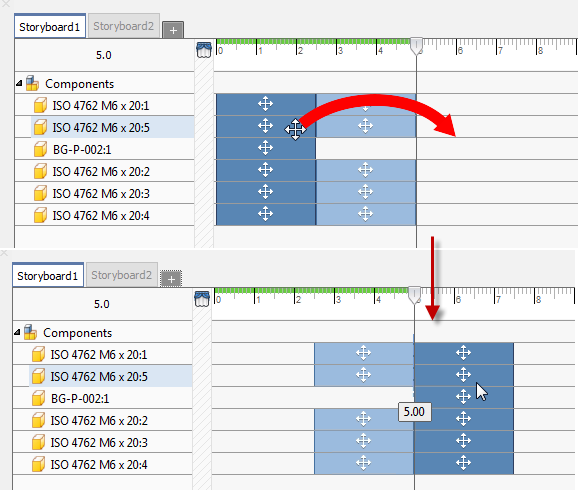
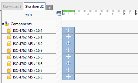
Multiple Action Editing
You can now edit multiple actions in various ways.
-
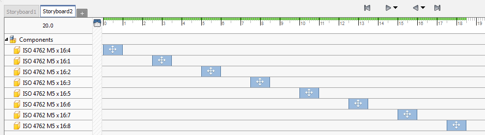
Move: Select multiple actions using Ctrl+click and then drag the selected actions to a different location on the timeline. You can drag to a position before or after other tweaks. Moving actions can be done with any selection of actions. When dragging actions with different start/end times, the selection set maintains the relationships.
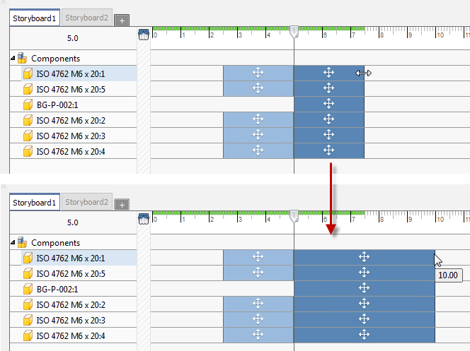
- Drag to Change Start/End Time:
Select multiple actions and modify the start or end time by dragging the cursor when the modify cursor appears. The actions do not have to share a time span.
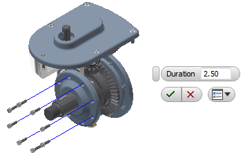
- Edit the Duration of Multiple Actions: Select the actions, right-click and choose Edit Time. Specify the Duration value and the selection set updates.
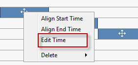
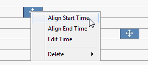
- Align Start/End Time:
Select multiple actions, right-click, and click Align Start Time or Align End Time.
- All Before, All After,and Group: You can select all actions occurring before or after the selected action or the playhead position. This makes it easy to increase the time between actions. The selection is based on the starting time of the selected action and includes all actions with matching start times. You can also select all members of a Group tweak from just one member.
- Edit Opacity: You can edit the opacity of one or more components. Components set to Transparent in the assembly carry that setting into Presentations. When editing multiple components, having different opacity settings, at the same time, the components all get the same opacity value setting.
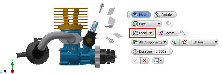
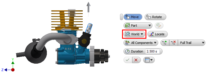
Local/World Direction
You can now specify tweak direction using the local (component) coordinate system or the world (presentation) coordinate system in the mini-toolbar. For multi-selection sets the local coordinate system aligns with the first object selected.
Publish Images with a Transparent Background
Select a Snapshot View to publish as an image. Click Raster
 . At the bottom of the dialog box, check the box for Transparent Background.
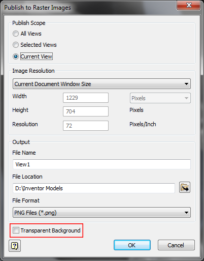
Publish Raster
When publishing an image, you can now select from a list of provided resolutions or specify the image resolution.
Expand/Collapse All Children in the Storyboard Panel
Use Expand or Collapse
Performance Improvements for Presentations
- Trail selection
- Component selection
- Multiple actor selection in the timeline panel
- Delete Tweaks
- Delete Storyboards
- Create storyboard from previous storyboard
Mesh components are supported in Presentations and are treated the same as solid components. They can be tweaked, have opacity changes, etc. and have actions in the timeline.
Auto Explode Removed
The Auto Explode command, found on the Select Assembly dialog box when using the Create View command, has been removed from Inventor 2017 Presentations.