Interoperability
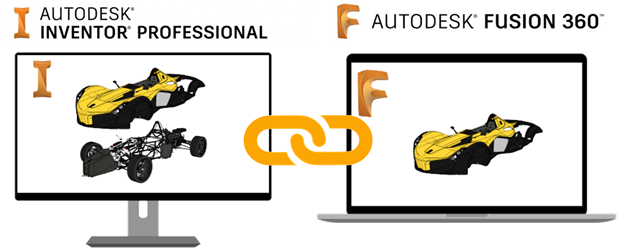
Move Data Between the Desktop and the Cloud: AnyCAD for Fusion 360
This new AnyCAD workflow allows you to take advantage of the power of Inventor and Fusion 360 together.
Overview
Inventor continues to expand AnyCAD functionality by adding support for Fusion 360 design files.
Bring Fusion 360 models directly into Inventor for system integration, large assembly design, and documentation. When the Fusion 360 design is updated, the changes can be consumed in Inventor.
Similarly, you can reference Inventor parts into Fusion 360 for cloud-enabled simulation, CAM, and more. Because Fusion 360 now uses the same AnyCAD technology, changes in the Inventor model can be automatically consumed in Fusion 360.
AnyCAD gives you the flexibility to use Inventor’s world class 3D mechanical engineering design capabilities with the Product Innovation Platform, giving you the power to make anything.
Getting Started
To share data between Inventor, a desktop application, and Fusion 360, a cloud based platform, there are a few things to set up and consider.
- Install
Desktop Connector. This piece enables you to move data between the desktop and the cloud.
Desktop Connector installs a desktop folder that provides direct access to the Fusion Team cloud space
 .
.
Download the Desktop Connector installer from your profile menu in your Fusion Team account.

- Identify a Fusion Team account to use for sharing data. Fusion Team provides a personal central workspace in a cloud hub for your projects.
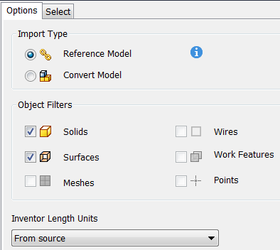
Import Fusion 360 (.fusiondesign) files as an AnyCAD Reference Model
Once set up, you can open/import Fusion 360 (.fusiondesign) files from your Fusion 360 drive
with an option to convert or create an AnyCAD reference. Importing a Fusion 360 (.fusiondesign) file as an AnyCAD reference model maintains a link to the selected file which enables you to monitor and update as the model changes. This workflow allows you to use Inventor data in Fusion 360 and Fusion 360 data in Inventor, allowing more flexible use of these tools as part of their product design and manufacturing process.
For more information, see To Import Fusion 360 Files as an AnyCAD Reference Model .
Support for Moving Points Attached to DWG Underlay Geometry
Previously, once you created a dimension on DWG Underlay geometry, the point that attaches to the geometry could not be attached to a different point. Now you can drag the dimension boundary line and attach the point to different geometry.
For more information, see To Work with Associative DWG Underlays in Drawings.
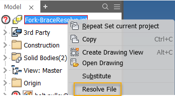
Resolve Missing AnyCAD References
Support for resolving references to missing AnyCAD files is extended to the AnyCAD workflow.
If you open a part or assembly file with missing references to one or more AnyCAD files, the Resolve Link dialog box displays so you can search to locate the missing reference(s). If you select to skip unresolved references, the Unresolved icon displays next to the top browser node in the open file. You can re-open the Resolve Link dialog by right-clicking the top node of the browser, and selecting the new context menu option Resolve File.
For more information on resolving missing references, see To Resolve Skipped Components and Resolve Link Reference.
For more information on supported file types and importing files as an AnyCAD reference, see About AnyCAD and Importing Files from other CAD Systems.
Parts
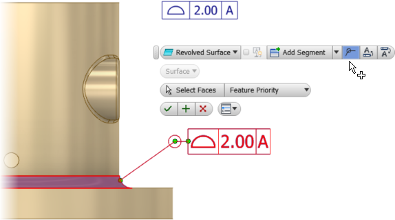
Model-based definition
The all-around symbol is added to Feature Control Frames (FCF) for Profile of a Surface.
For more information, see About 3D Annotation and Model-Based Definition.
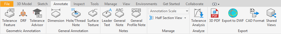
Export to DWF
Support for 3D Annotations is added to DWF Export. For easy access, the Export to DWF command is added to the Export panel in the part and assembly Annotation tab. Invisible annotations are exported as hidden in the DWF, but their visibility can be toggled on in the exported DWF file.
For more information, see To Publish 2D and 3D Models to DWF and Share with Reviewers.
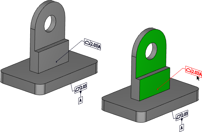
3D PDF export
Exported 3D PDF files now support associative face highlight for tolerance annotations that reference multiple faces.
For more information, see To Export a Model to 3D PDF.
Sheet Metal Parts
Sync Unfold Rule
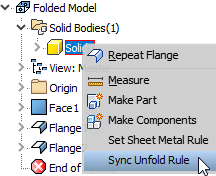
Inventor lets you specify different unfold rules for features in a body, but there was no easy way to sync all features to use the same rule if you changed your mind. This release introduces a new command that lets you sync all features to use the same unfold rule with one click.
- Right-click a body in the browser and select Sync Unfold Rule.
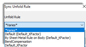
- In the dialog, select the desired rule for all features and click OK.
For more information, see To Add, Edit, or Sync a Sheet Metal Unfold Rule
Assemblies
Ground and Root Enhancement
Previously, with a single click, the Assemble  Productivity Ground and Root Component
command grounded, moved, and used flush constraints to root the selected component to the origin of the assembly; then it repositioned the component to the top of the browser.
Productivity Ground and Root Component
command grounded, moved, and used flush constraints to root the selected component to the origin of the assembly; then it repositioned the component to the top of the browser.
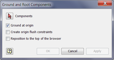
The command is renamed Ground and Root and now opens a dialog box and presents the above operations as separate options.
In addition, the Ground and Root command supports multiple selections. You can select one or more components, and then select one or more options in the new Ground and Root Components dialog box.
- Ground at origin: Moves, grounds, and aligns the selected component(s) to the origin of the assembly. The component(s) can be freely moved if you unground the component(s).
- Create origin flush constraints: Applies flush constraints to root the component(s) to the origin of the assembly.
- Reposition to the top of the browser: Repositions the selected component(s) to the top of the assembly browser.

For more information see, Ground and Root.
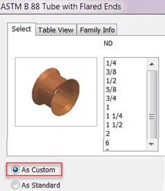
Content Center Save Enhancement
Previously when you changed the size of a content center member as a custom part, Inventor saved the change automatically. Save for custom parts now operates in the same way as it does for other parts: The changes are only saved if you save changes to the file.
Example
For more information, see Family Reference.
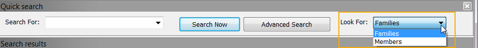
Content Center Quick Search Enhancement
You can now perform a quick search for Members: A new drop down menu, Look For (Families or Members) is added to the Content Center Editor and Place from Content Center dialog box. This allows you to perform a quick search for Members. With the Members option selected you can, for example, enter a part number in the Search For field, and perform a search for a specific Part Number.
For more information, see To Search in the Content Center Database.
Improved Preview for Assembly Chamfer
Previously, when you created/edited a chamfer only slant lines were used to provide a preview of the chamfer in the graphics window. Preview is improved and more clearly displays the part of the edge that creates the chamfer or partial chamfer.
For more information, see To Create Chamfers and Partial Chamfers.
Sketch
Use the new setting, Tools tab Options panel Application Options/Sketch tab
Auto-scale sketch geometry on initial dimension, to control how sketch features are scaled (auto-scale).
Auto-scale maintains the original shape of a sketch when adding the first dimension. Deselect this option when you do not want the distance between the sketch origin and geometries auto-scaled.
For more information see, Sketch Tab Reference (Application Options).
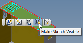
Sketch Visibility Icon Added to Mini-Toolbar
Use the new visibility icon on the 2D sketch mini-toolbar to toggle on and off the visibility of a sketch when selecting an associated face in the graphics window.
For more information on sketching, see To Work with Sketches.
Drawings
Hatch Creation Enhancement
Previously, you could only add one Hatch Region at a time in Drawing Sketches. You can now select multiple closed profiles in a sketch, and apply the Fill/Hatch to all of them.
For more information on hatch creation, see To Add and Edit a Hatch to Drawing Sketches.
Split Table Help Updated
Customer feedback directed our attention to the split table help. The help topic did not properly explain the process of splitting a parts list and moving the split section to a new sheet. The help is updated for this release.
For more information, see To Split a Table
- Collate is added as an option to the Print Drawing dialog box. The new
Collate option is available when the drawing has more than 1 sheet, and you specify to print 2 or more copies.
For more information see, Print Dialog Reference.
- Drawing view update performance is improved. Inventor 2018.1 sped up drawing view updates by processing edits only for the portion of the drawing view that is changed. Further improvements make drawing view updates faster in scenarios where views are updated after many parts have been edited.
iLogic
Autocomplete Enabled in the Rule Editor
Autocomplete is enabled for the following:
- Inventor parameters
- iLogic objects and functions
- Inventor API objects
- .NET objects
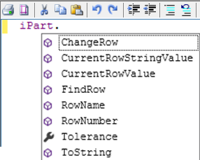
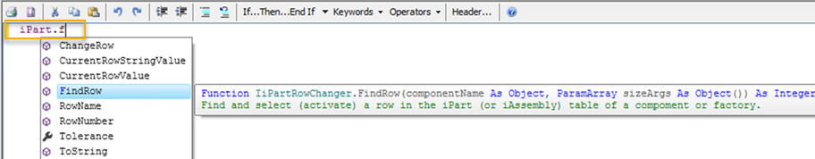
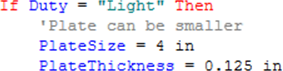
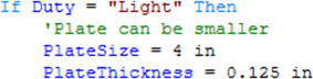
For example, type "." after a variable and begin typing; or type Control-Space or Alt-RightArrow at any time. As you type, a list of available selections display in alphabetical order. A full description of the variable displays in a tooltip.
| A drop-down list of properties and methods displays after you enter "." | Begin typing after entering "." and autocomplete displays available selections. |
|
|
For more information, see To Work with Rules in iLogic.
Other iLogic Enhancements
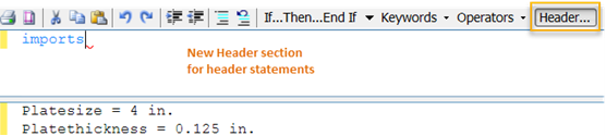
- Use the new
Header section in the Rules Editor to create header text. Header text can only be created in the Header section. If you add header statements, the Header section remains open the next time you access the Rule Editor. The new autocomplete behavior also functions in this section.
- Use the new option,
Syntax coloring, on the Options tab in the Rule Editor to set the color scheme. You can select between Classic and Modern.
Rule Editor Options tab Example of the new syntax coloring 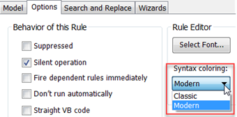
Classic
Modern
- You can now use the shortcut key, CTRL+S to save a rule in the Rule Editor.
For more information, see To Work with Rules in iLogic.
General
Support for Editing Suppressed Constraints
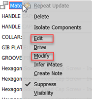
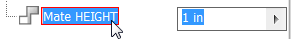
You can now edit, modify, and quick edit a suppressed constraint. To edit or modify a value, right-click on a suppressed constraint in the browser and select Edit or Modify. To open the quick edit box, click on a suppressed constraint in the browser.
When you edit a suppress constraint:
- The browser nodes are updated with the new values.
- The edited constraint remains suppressed and unsolved in the assembly.
Attention: If you update a suppressed constraint with a new parameter used by another feature in the assembly, the updated value will be used by the assembly.
Preview is not available for the suppressed constraint.
| Edit and Modify | Quick edit |
|
|
For more information see, About Deleting and Suppressing Features.
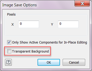
Export PNG, TIFF and BMP Image Enhancement
You can now export an Inventor file as a:
- PNG or TIFF image with a transparent background
- BMP image with a white background
For more information see, Saving and Exporting Files Reference.
Measure Enhancement
The function for accumulating measurement values is back and improved. You can now add the values of linear, area, volume, and angle measurements and calculate a total measurement for each of these 4 types.
Workflow Overview
Begin by opening
Tools
tab
Measure panel Measure.
- Make a selection in the graphics window, and then select the plus sign next to a measurement type. For example, select a line, and then select the plus sign (Add to Accumulated Value) next to Length.
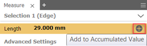
- The length value is added to the Distance measurement group under Accumulated Properties. The plus sign ( Add to Accumulated Value), adds selections to the Accumulated Properties group for every type of measurement you click to accumulate.
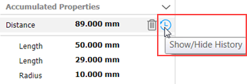
Try it: Select another line in the graphics window and then click the plus sign next to length. Select a radius and then click the plus sign next to the radius. Click Show/Hide History next to Distance to display the values you just added.
Summary
For every measurement type you want to accumulate, first make a selection in the graphics window, and then click the plus sign. Each measurement is added to the accumulated properties group associated to measurement type of the selection.
Each value can be quickly added to or deleted from the accumulated list. Each accumulated property group can be individually deleted. The list of selected values can be hidden or displayed. Use the context menu to copy individual or total values to the clipboard. All accumulated properties are cleared when the measure command is closed.
Watch this short video to learn how to accumulate values of measurements and use Show/Hide History to display accumulated values.
For a closer look at Show/Hide History and deleting accumulated values, watch this short video.
For more information, see To Accumulate Values of Several Measurements.