Inventor 2017.3 delivers fixes and over 20 product enhancements in projected sketch references, intelligent interference filtering, 3D PDF publishing, additional BIM OmniClass product codes, and enhancements directly from customer Inventor Ideas feedback. This update also provides the next step in product learning with a unified learning experience that enables customers to create, manage and publish learning content with Guided Tutorials.
General
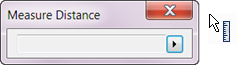
Measure Enhancements
- Easily restart Measure by clicking in the graphics window.
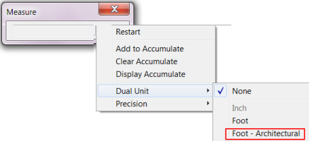
- A Dual Unit,
Foot - Architectural, is now available for Measure Distance, Loop, and Area.
Note: Fractions smaller than 1/128 are not supported.
For more information about Measure, see To Measure Distance, Angle, Loop, or Area in Model.
Additional Workflow Enhancement
You can now use a crossing window to select multiple closed profiles when creating features with the Revolve, Sweep, Coil, Chamfer, and Fillet commands.
3D PDF
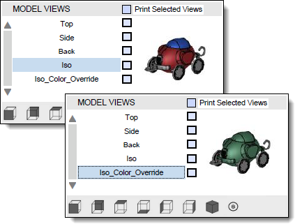
3D PDF export is significantly faster and now supports View representation color overrides.
Sketch
Select Tangencies Now Available within Project Geometry Command
- With the left mouse button, double-click a face or an edge.
- Select a face or an edge, right-click, and select Select Tangencies from the context menu.
OR
For more information, see Select Command Reference.
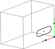
Projected Sketch References are Now Maintained After Redefining a Sketch
Previously if you redefined the plane that a part or assembly sketch was created on, the projected references were lost (sketch turned green).
Now if you redefine the sketch plane, the associativity is maintained (sketch remains yellow). This applies to the following types of sketch references:
- Projected Geometry.
- Projected Loop.
- Cut Edge.
- Cross part reference.
Redefine Tips
- When you redefine a sketch plane the sketch origin is translated by following the sketch normal and sketch axis with the least amount of rotation.
Original sketch coordinate system Redefined sketch coordinate system 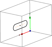
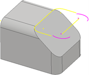
- If you redefine a sketch to a non-parallel plane, the sketch may be marked as sick the on projected geometry while its geometry type is changing. In these cases, manually delete the sick geometry and project them again.
Spline projected geometry Spline projected geometry redefined as arc 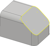
- If a downstream feature fails after you redefine a consumed sketch of a feature, edit the downstream feature as needed.
For more information, see About Projecting Sketch Geometry.
New Options in Application Options  Sketch tab Enhance Performance
There are now separate settings for controlling the Look at behavior in an assembly sketch and controlling the Look at behavior in a part sketch in the Applications Option dialog box Sketch tab.
Now that there are separate settings for part sketch and assembly sketch, you can, for example, disable looking at the sketch plane when editing a component and have Look at enabled when editing an Assembly sketch.
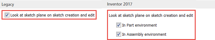
- When creating or editing a part sketch.
- When creating or editing a component in part.
- During in-place edit of a part within an assembly.
The setting In Assembly Environment controls Look at behavior when creating or editing an assembly sketch.
For more information, see Sketch Tab Reference (Application Options).
New 3D Sketch Mini-Toolbar and 2D Sketch Mini-Toolbar Options
A mini-toolbar is added to the 3D sketch environment.
 Edit 3D Sketch: Displays when selecting a 3D sketch in the part and sheet metal environment.
Additionally, the following options are added to the new 3D sketch mini-toolbar and to the existing 2D sketch mini-toolbar. The following options display when selecting a 2D or 3D sketch based feature:
 Share Sketch: Displays when selecting sketch and sketch based feature/face in the part and sheet metal environment and the sketch is not shared.
 Unshare Sketch: Displays when selecting sketch and sketch based feature/face in the part and sheet metal environment and the sketch is shared.
 Make visible: Displays in all part and assembly environments and visibility is off.
 Make invisible: Displays in all part and assembly environments and visibility is on.
For more information on sharing and un-sharing sketches, see To Create and Edit Sketches.
For more information on sketched features, see About Sketched Features.

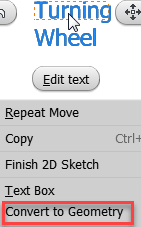
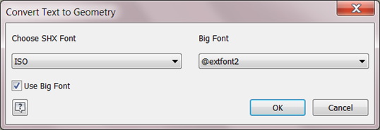
Convert Sketch Text to Geometry
You can now convert part, assembly, and drawing sketch text into sketch geometry (lines, arcs). Use converted text geometry to create text engravings, for example, to laser etch part numbers or stock information onto models.
After the text is converted to standard sketch geometry, the converted geometry is no longer associative with the original text.
| 1. Right-click the sketch text. | 2. Make selections. | 3. Text is converted to standard geometry. |
|
|

|
For more information, see To Convert Sketch Text to Sketch Geometry.
Assemblies
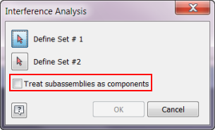
Multiple Enhancements to Analyze Interference
- The new option in
Interference Analysis dialog box,
Treat subassemblies as components, lets you treat sub-assemblies as single components and ignore the interferences within the sub-assemblies.
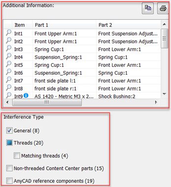
- The
Interference Detected
dialog box now includes:
- Information about each interference.
- Interference type filtering options. Focus on the information you need to check by including only the interferences you want to see.
Note: The AnyCAD reference components filter displays when the assembly includes an AnyCAD reference..
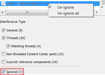
- Ignore and Un-ignore options. You can:
- Right-click an item and select to ignore the selected volume or ignore all interference volumes less than a selected value.
- Select or deselect the Ignored filter to show or hide the ignored interferences in the list.
Note: An ignored interference is displayed with a cross line.
- Right-click an ignored interference and select to Un-ignore the selected item, or Un-ignore all.

- Mismatched threads display the interference type in a tooltip for 4 interference types.
- Threaded components are misaligned.
- Thread designation does not match, including nominal diameter, and pitch.
- Left/Right hand does not match.
- Thread length does not match.
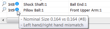 Note: The first set of numbers in the tooltip indicates Internal thread value. The second set indicate the External thread value.
 - The interference type is included in a new column called Note when you copy
 a thread interference value into Excel.

For more information, see To Analyze Interference Among Components.
Assembly Shrinkwrap Options Dialog Box Enhancement
The setting, Use color override from source component, is now available in the Assembly Shrinkwrap Options Dialog Box. Use this option to link color from the base component into the target part. If unchecked, the appearance is set to the default appearance of the target part.
The label for the option, Use color override from source component, in Application Options Part tab is renamed to
Make/Derive/Shrinkwrap
For more information, see Create a Shrinkwrap Part.
Guided Tutorial Author
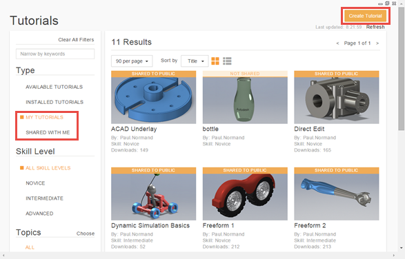
Create and Share Tutorials
You can now create your own tutorials and share them publicly or privately. This enhancement adds two new categories to Type. Click My Tutorials to display and manage tutorials you create. Click Shared With Me to display tutorials that are shared privately with you.
When you click Create Tutorial to start the authoring process, the Anatomy of a Tutorial visual guide is displayed. Click the How to links on the Anatomy page to watch two short videos that guide you through the create and share process.
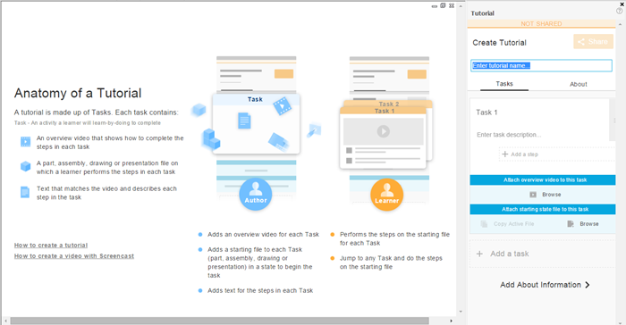
For more information on Guided Tutorials, see Get Started Tutorials.
BIM Content
Preparing BIM Content for Configurator 360
A new workflow is provided for preparing Inventor models for use as BIM Content via Configurator 360. See About Preparing an Inventor Assembly for BIM Content on Demand.
OmniClass 2006 Support
- 23.10 Site Products
- 23.20 General Purpose Construction Accessories and Surfacing Products
- 23.25 Structural and Space Division Products
- 23.35 Covering, Cladding, and Finishes
Switch from OmniClass 2006 to OmniClass 2012
The Categories.xml file contains the OmniClass 2006 classifications and the mapping to Revit categories. If you want to use OmniClass 2012 classifications you can change from 2006 to 2012 by following these instructions.