This example illustrates how to generate a thermo-mechanical process parameter file, known as a PRM file. A PRM simulation models a small amount of material to determine how a certain material will thermo-mechanically respond to a certain set of processing parameters. This information gets encoded in the PRM file, which is read by subsequent part-level analyses for builds using the same material and processing parameters.
This example will also guide you through the production of post-process time-temperature, and time-displacement data files for selected points, which can be used to plot thermal or displacement results.
For instruction on how to produce a thermal PRM file, to investigate lack of fusion and hotspot behavior, see Example 14.
Sample files for use with the examples are available in the Local_Simulation_example_Files_2021.1.zip package from this Download Link. Expand the downloaded ZIP archive into a convenient directory from which you can run Local Simulation inside the numbered directories.
For this example, you will run commands inside directory 01.
Problem description
In order to run Part-Level Powder-Bed analysis in Local Simulation, a process parameter (PRM) file must first be generated. The PRM file links the small scale moving-source analysis to the full part-level analysis. This is illustrated in Figure 1 below.
To create accurate PRM files, which will result in accurate part scale models, PRM generation must be performed using the prm_gen program. Merely running the small scale simulations without using prm_gen will leave out key portions of the PRM generation process which will produce an inaccurate PRM file.
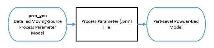
Figure 1: Relationship between the fine scale and part-level analyses
Here, a process parameter file is generated for Inconel® 625 using the following set of parameters:
- Power: 150 W
- Laser spot size: 0.15 mm
- Scan speed: 600 mm/s
- Layer thickness: 0.04 mm
- Hatch spacing: 0.15 mm
- Recoater time: 20 s
- Initial angle rotation: 11.5 degrees
- Interlayer hatch angle rotation: 67 degrees
The parameters are entered into the *LSRP card. The *GTAB card is used to output and name the process parameter file. The flow of the analysis is shown in Figure 2.
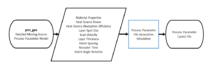
Figure 2: Flowchart for generating PRM files
A time incremental thermal analysis is performed first to compute the temperature history of the part followed by a time incremental mechanical analysis. The PRM file is filled out for several different section thicknesses and temperatures. The thickness of a section is controlled by using the 10th input of the *LSRP card and the temperature is controlled by using the *INIT card. Once the full table is filled out in the PRM file, the file can be input along with geometric information for the Part-Level analysis as illustrated in Figure 3. Part-Level analyses are demonstrated in later examples in this help system.
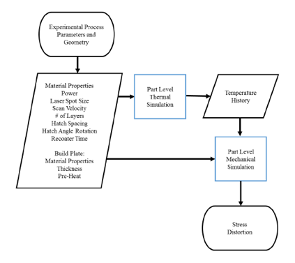
Figure 3: Flowchart for generating PRM file
Running Netfabb Simulation
- From a command line run
$ prm_gen 01_thermal.in 01_mechanical.in > prmgen.out
Users can check the progress of the simulation by viewing the log file, which is recorded in prmgen.out.
The result of the analysis will be a single process parameter (PRM) file. The file will be read into succeeding Powder-Bed Part-Level analyses.
Post Processing
A tool for producing temporal results, timex, is included in the installation. This program uses an input text file with the following entries:
*INPU
a1 = input-file-name (without *.in extension)
*PNTS
i1 = Number of points to probe
r11, r12, r13 = X, Y, Z coordinates, point 1
r21, r22, r23 = X, Y, Z coordinates, point 2
...
Two timex input files are included, timex-temp.txt and timex-disp.txt, which probe the thermal and mechanical results at several locations, respectively.
To produce a temperature history for selected points, from the command run:
$ timex timex-temp.txt
The resulting comma-separated text file is called timex_prmgen_thermal.txt. It has the format: Time (s), Temp at Point 1, Temp at Point 2, Temp at Point 3, ...
View the timex_prmgen_thermal.txt file in the text editor of your choice. Note that for locations which are in the deposition region, temperatures are 0 until the associated element has been activated. This data is easy to plot in any spreadsheet software or programming environment.
To produce a displacement history for selected points, from the command run:
$ timex timex-disp.txt
The resulting comma-separated text file is called timex_prmgen_mechanical.txt. It has the format: Time (s), Point 1 Displacement Magnitude, Point 1 X Displacement, Point 1 Y Displacement, Point 1 Z Displacement, Point 2 ....
Open up the timex_prmgen_mechanical.txt file. Note similarly to the thermal results; all displacements are set to 0 before the element has been activated.