Use the High speed page to improve the smoothness of the wireframe swarf toolpath.
Arc fit corners — Select tocreate arcs in all internal corners.
This example looks at a constant Z toolpath, but the principles are the same for all toolpaths.
- When Arc fit corners is deselected, sharpening is carried out on all internal corners.
- When Arc fit corners is selected for the same example, arcs are created in all internal corners, using the Radius specified:
Radius (tool diameter units) — Specify the radius used if you select Arc fit corners. The radius is defined as a proportion of the tool diameter. The default value is 0.05. So, if you have a tool of diameter 10 mm (radius 5 mm), then the arc radius will be 0.5 mm.
Vertical smoothing
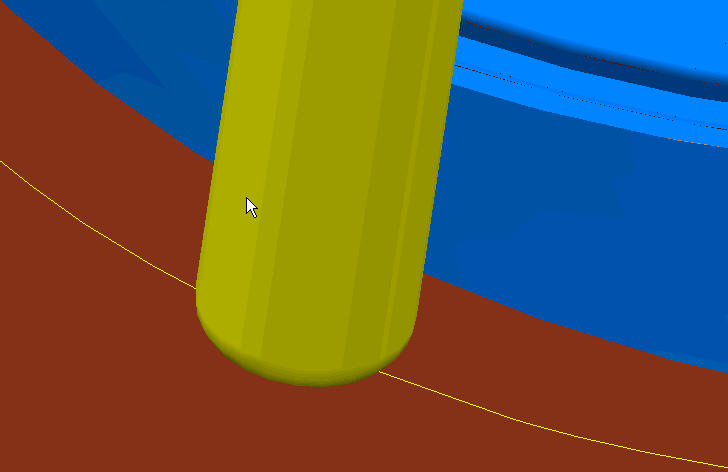
Up/Down axis (tool diameter units) — Enter the toolpath smoothing distance. The toolpath is smoothed up/down the tool axis. It is effective in removing excessive "judder" caused by offsetting in internal corners. It is best to try smoothing with the default values initially: too much smoothing can flatten the profile unduly.
Axis calculation tolerance — Enter a tolerance value for calculating the tool axis. For a relatively rare number of geometries, the tool axis can waver slightly as it positions accurately on the surfaces to be machined. This can be due to small but significant changes in the geometry as the tool moves from one position to another. This tolerance can be larger than the machining tolerance to stabilize the tool axis as it moves across this geometrically varying region. As a consequence excess material may be left on the surface but the load on the tool may be reduced.
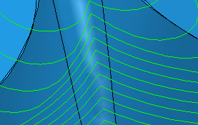
- With Axis calculation tolerance the same as the machining Tolerance:
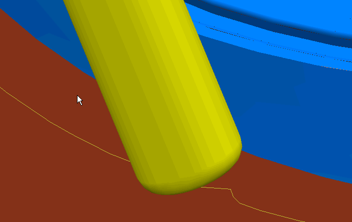
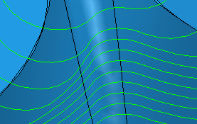
- With Axis calculation tolerance increased to 0.5: