Use the Tool orientation page to control the orientation of the tool in 4-axis simultaneous toolpaths.
The following settings are available:
Type — Select an option to define the tool orientation. The options available for selection vary depending on the surface machining strategy being used.
- Automatic — PartMaker uses the geometry to determine the tool axis. This option is available when using Swarf or Wireframe swarf finishing strategies.
- Vertical — The tool is perpendicular to the active Face plane. This option is available when using Raster, 3D Offset or Pattern finishing strategies.
The following images show the Vertical tool axis type in reference to the machining plane:
Tool orientation: Vertical
Orientation angle (A): 0

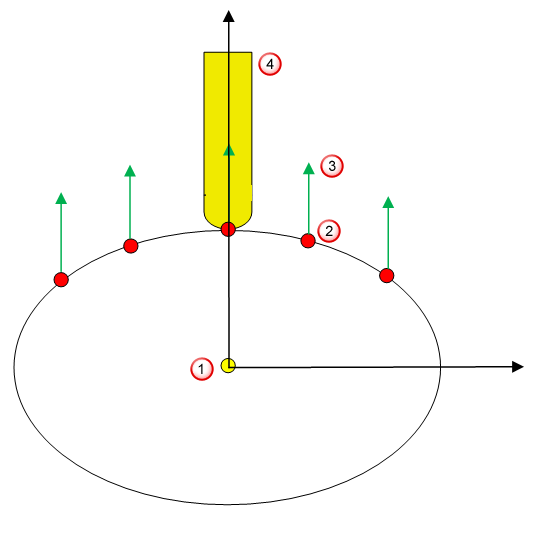
 Rotary axis
 Toolpath point
 Tool axis at a given toolpath point
 Tool
ToolTool orientation: Vertical
Orientation angle (A): Set to a value other than 0
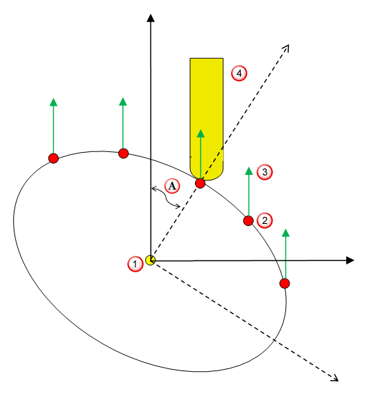 Rotary axis Toolpath point Tool axis at a given toolpath point Tool
  Orientation angle
 - Radial — The tool points towards the rotary axis. This option is available when using Raster, 3D Offset, Spine, or Pattern finishing strategies.
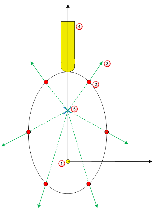
The following image shows the Radial tool axis type in reference to the machining plane:
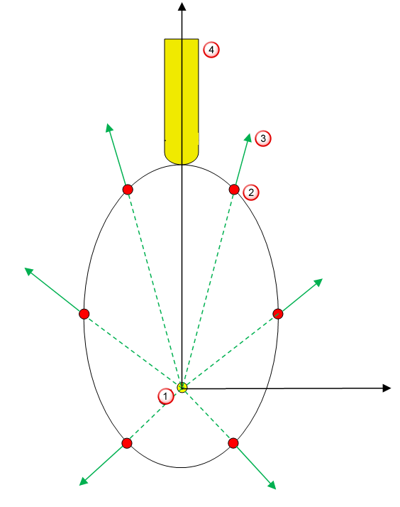 Rotary axis Toolpath point Tool axis at a given toolpath point Tool
 - Towards surface — The tool points towards the surface being machined. This option is available when using Raster, 3D Offset, Spine, or Pattern finishing strategies.
The following image represents the Towards surface tool axis type at a cross-section plane parallel to the machining plane:
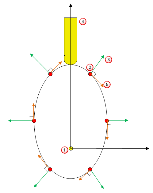 Rotary axis Toolpath point Tool axis at a given toolpath point Tool
 Surface tangent
This option is not available when using the Pattern finishing strategy with a Base position of Drive curve.
- Towards spine — The tool is oriented towards the Spine curve. This option is available when using the Spine finishing strategy.
The following image represents the Towards spine tool axis type at a cross section plane parallel to the machining plane:
 Rotary axis Toolpath point Tool axis at a given toolpath point Tool Intersection of spine curve with the cross-section plane
Orientation angle (A) — Enter an optional stock rotation angle, which PartMaker applies after calculating the toolpath that achieves the desired tool orientation. You can use this angle to control the tool contact point and so achieve a better surface finish.