When using the Profile Group Parameters dialog for a Face Mill strategy, the following settings are available:
Style — Select the style you want to use:
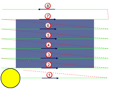
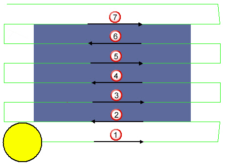
- Linear — Select to cut the face starting from one end of the stock and progressing to the other end. Select the Toolpath direction for a Linear style from:
- Uni-Directional
Depending on the stepover, the last pass of the path may be in the opposite direction to facilitate the removal of burrs.
- Bi-Directional
- Uni-Directional
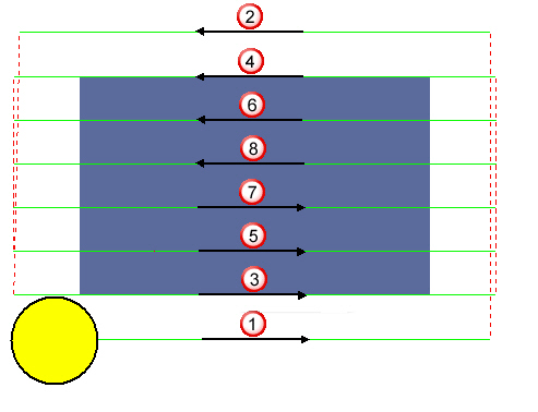
- Spiral — Select to cut the part starting from one end of the stock and machining a pass. It then jumps to the other end of the stock and machines a pass. It continues this pattern until it reaches the middle of the face.
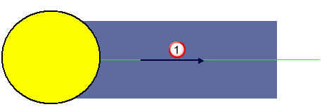
- Single Pass — Select to machine the part in one single pass at the center of the face. It is intended for a tool that is larger than the face.
Toolpath Direction — Select the direction of the toolpath. This is available only when Linear is selected as the Style.
- Uni-Directional — Select to machine the toolpath in the same direction between each pass.
- Bi-Directional — Select so machining of the toolpath alternates between climb and conventional milling between each pass.
Z_Surf (S) — Enter the signed distance from the zero reference point to the part surface.
Z_Depth (D) — Enter the depth of the operation to be performed.
Z_Rapid (R) — Enter the distance between the bottom tip of the tool and the part surface when a tool performs rapid moves.
Z_Clear (Cl) — Enter the distance between the bottom tip of the tool and the part surface when a tool starts feeding into the part.
Bottom Finish (b) — Enter the amount of material left on the bottom for finishing if the Finishing option is selected.
Cutting Area Expansion (e) — Enter a value by which the area to be machined is expanded by on all sides. For example, if a 1.0 inch by 1.0 inch block is to be machined with a Cutting Area Expansion set to .25 inch, then PartMaker machines a block that is 1.5 inches by 1.5 inches.
Angle (A) — Enter the angle to the X axis formed by the toolpath.
Operations information
- Roughing — Select this option to include a roughing pass operation.
- Finishing — Select this option to include the finishing pass operation.
- Diam (d) — Enter the diameter of the tool used to perform the selected operations, for example Roughing and Finishing operations.
- Tool ID — Enter the ID of the selected tool. When you have saved the group, you can click the icon showing a representation of the tool (for example
 ) to display the Edit Tool dialog to view, or modify, details of the tool.
 - Width of Cut — Enter the width of the cut for the operation. This value can be calculated as a percentage of the diameter of the tool selected for the operation or specified as an absolute value, depending on the Width of Cut and Width of Cut Value settings on the Defaults for Milling dialog.
- Axial Step — Enter the axial step of the tool. By default, PartMaker uses the Axial Step value specified in the tool's properties in the Tools Data dialog. If the axial step is set to zero, the material is removed in a single axial step.
Lock Toolpath —Select this option to lock the toolpath. When a toolpath is locked, PartMaker does not recalculate it even if its settings on the Profile Group Parameters dialog change. Deselecting this option unlocks the toolpath.
Polar Style Output — Select this option to specify whether the NC program is in polar format. This allows for Posts to explicitly support machining without polar interpolation activated in the NC code. This option is available only when using a Mill End, Polar Face window.
- When selected, the post will typically output X and Y positions with polar interpolation activated.
- When deselected, the Post will typically output Radius and C-angle positions without polar interpolation.
Group Name — Enter a name for the profile group.
Select Tools — Click to display the Select Tool dialog, where you can select the tool to use for machining.
Extract Parameters From Solid — Select this option to extract geometric information from the imported solid model and use this information to complete some of the fields on this dialog. When you have selected this option, select surfaces on the solid model and then click Extract to extract the geometric information. Press the Shift key to select more than one surface at a time. Click Undo to revert any values on the dialog that have been calculated by extracting geometric data from the solid model back to their original values.