Geometric PLP alignments enable you to align a part to its model using a plane, line, and point for which you know the nominal coordinates. This type of alignment allows you to use any method of creating the component items. It also allows you to modify the alignment by amending the details of the geometric items or by remeasuring them individually.
To create the alignment:
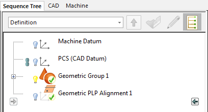
- Click Up
 at the top of the Sequence Tree to close the geometric group.
 The Active Group list changes to Definition to show you have closed the group and are working at the top-level of the inspection sequence. The in-tolerance
 icon is displayed on the group to indicate the measurement status of the items it contains.
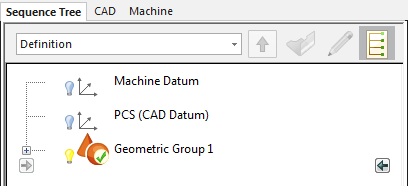
- Click Home tab > Create panel > Alignment arrow > Geometric PLP.
The Geometric PLP Alignment dialog is displayed. In the:
- Plane area, Oriented normal is Z/Z+ to indicate the positive direction of the Z axis is the same as the direction of the specified plane's normal vector (up from the part).
- Line area, Orientated direction is X/X+ to indicate the positive X direction is in the direction of the specified line.
- Point area, the XYZ boxes are set to the location of the selected point item: Circle1::Centre.
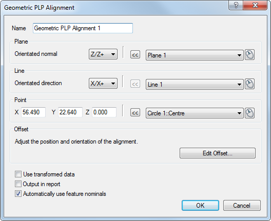
- In the Line area, select Line 1, then click OK.
This creates the alignment and adds it to the inspection sequence.