The first item to be measured in a Geometric PLP Alignment is the plane. In this example, the probed plane is used to specify the orientation of the part's Z plane.
To create a probed plane:
- Click Home tab > Create panel > Geometry > Probed Plane.
The Probed Plane dialog is displayed. Like the Geometric Group dialog, it specifies the name of the item, the coordinate system in which the results are reported, and the measurement tolerances for the item.
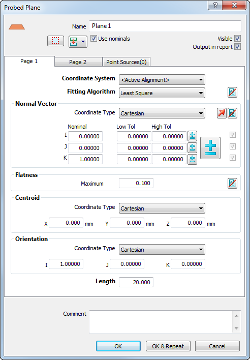
- Click OK to accept the defaults.
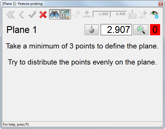
The Feature Probing dialog is displayed. It shows the name of the geometric item you are probing; the diameter of the probe; the number of points you have probed; and the minimum number of probe points required to measure the feature.
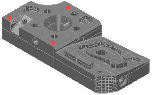
- Probe three points on the part, as shown:
When you have taken the third point, the background of the point count changes from red to green to indicate you have taken enough points to measure the plane.

- Click OK
 with the mouse to accept the points.