Use the synchronization process via Robot-AdvanceSteel Link to update the Advance Steel model with changes made in Robot.
Synchronization is a process that allows you to update your modifications using the .smlx format, without having to re-import the entire structure.
Synchronization workflow:
- Export your model from Advance Steel to Robot through the extension, using the .smlx format.
- If you make modifications to the model in Robot, re-export the modified model from Robot to a different .smlx file.
- Go back to your model in
Advance Steel, select
Export & Import Tab
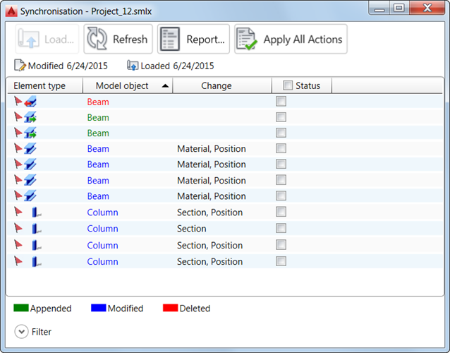
 Exchange Formats panel Advance Synchronization, and load the modified
.smlx file.
Exchange Formats panel Advance Synchronization, and load the modified
.smlx file.
- The modified .smlx file is compared to the already loaded model. All modifications between the two versions of the model are displayed. The modifications for each object will appear in a list which can be filtered.
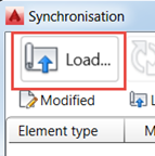
- The synchronization marks all the new objects as appended, and the existing objects that had geometrical changes (sections, materials, position, and so on) as modified.
- You can apply the modifications partially or totally. To do it, after selecting the modifications, click Apply All Actions.
To quickly select a number of objects, you can use a selection group. See To Use a Selection Group.
Synchronization dialog
In the Synchronization dialog, select:
- Status main tick box to accept all modifications for all objects.
- Main tick boxes such as Section-File or Material-File to accept modifications of sections or materials for all objects.
- Individual tick boxes in the modification line to select changes to apply.
Modified objects display in blue. Information about the scope of modification displays in the Change column. To view details of individual modifications:
- Left-click the header of the Change column and select
 Add column File, and then select a data item from the list, such as section - file, material - file, and so on. It displays another column with information about the selected data from the last transfer to
Robot.
Add column File, and then select a data item from the list, such as section - file, material - file, and so on. It displays another column with information about the selected data from the last transfer to
Robot.
- Left-click the header of the Change column and select
Add column Model, and then select a data item from the list, such as section, material, and so on. It displays another column with information about the selected data in the
Advance Steel model.
Main tick boxes with applied filters
The Main tick boxes work with applied filters. If objects are selected using the filters and a main tick box is activated, only those lines will have the individual tick box selected. It is illustrated in the following images.
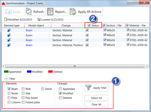
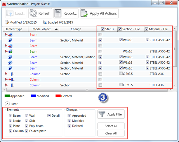
- You selected modified beams to be displayed.
- You selected Status main tick box.
- You displayed all objects again.
Only the lines with modified beams have the individual tick boxes selected.
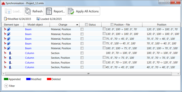
Position display in Synchronization dialog
You are prompted with the coordinate points of the start and end points of the object axis. It applies to all linear elements. Straight axes are defined by 2 points with the following syntax: 0',0'',0'->100',0'',0'.