Beam Cross-Section Property
Description: Defines the properties of a beam element by cross-sectional dimensions.
Format: (Note: n = number of dimensions and m = number of intermediate stations)

Example:

| Field | Definition | Type | Default | ||||
|---|---|---|---|---|---|---|---|
| PID | Property identification number. | Integer > 0 | Required | ||||
| MID | Material identification number. See Remark 2. | Integer > 0 | Required | ||||
| TYPE | Cross-section type. Must be one of following character variables: BAR, BOX, BOX1, CHAN, CHAN1, CHAN2, CROSS, H, HAT, HEXA, I, I1, L, ROD, T, T1, T2, TUBE, or Z. See Remark 5. | Character | Required | ||||
| F0 | Preload. | Real or blank | 0.0 | ||||
| DIMi(A), DIMi(B) | Cross-sectional dimensions at end A and B. | Real > 0.0 | Required | ||||
| NSM(A), NSM(B) | Nonstructural mass per unit length. | Real or blank | 0.0 | ||||
| SO(j), SO(B) | Stress output request option for intermediate station j and end B.
|
Character | YES | ||||
| X(j)/XB | Distance from end A to intermediate station j in the element coordinate system divided by the length of the element. | Real or blank | 1.0 | ||||
| NSM(j) | Nonstructural mass per unit length at intermediate station j. | Real or blank | 0.0 | ||||
| DIMi(j) | Cross-section dimensions at intermediate station j. | Real > 0.0 | Required |
Remarks:
- PID must be unique with respect to all other PBEAM and PBEAML property identification numbers.
- For structural problems, PBEAML entries must reference a MAT1 material entry.
- See the PBEAM entry description for a discussion of beam-element geometry.
- If any of the fields NSM(B), DIMi(B) are blank on the continuation entry for End B, the values are set to the values given for end A.
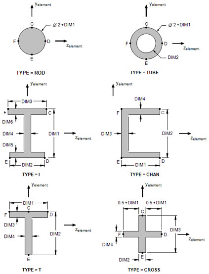
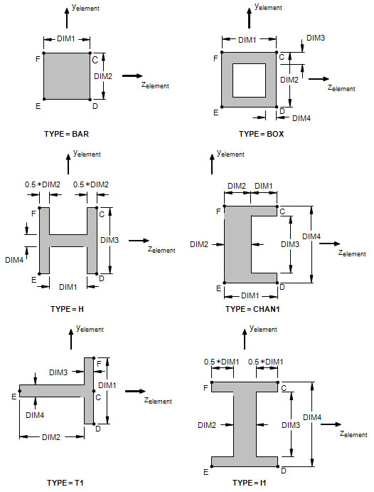
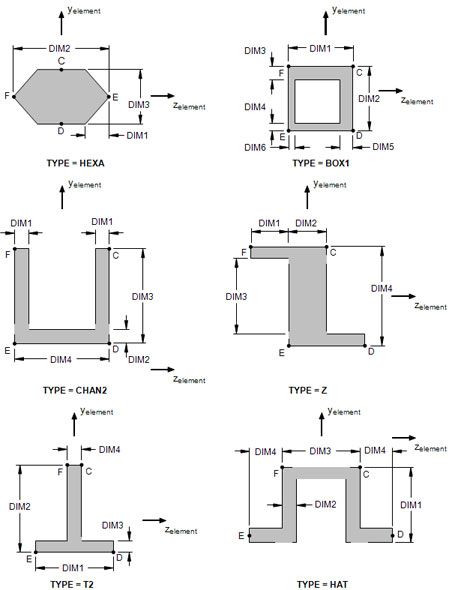
- The cross-sectional properties, shear flexibility factors, and stress recovery points (C, D, E, and F) are computed using the TYPE and DIMi as shown in Figure 1. The origin of element coordinate system is centered at the shear center of the cross-section oriented as shown.
- A function of this entry is to derive equivalent an equivalent internal PBEAM entry. This equivalent entry is given in the database definition section of the Model Results Output File and in the translated Bulk Data Output File.

Figure 1a. Definition of Cross-Section Geometry and Stress Recovery Points

Figure 1b. Definition of Cross-Section Geometry and Stress Recovery Points

Figure 1c. Definition of Cross-Section Geometry and Stress Recovery Points

Figure 1d. Definition of Cross-Section Geometry and Stress Recovery Points