Beam Element Connection
Description: Defines a beam element.
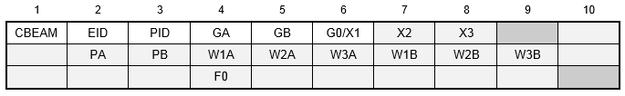
Format:
Example:

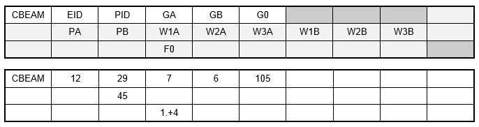
Alternate Format and Example:
| Field | Definition | Type | Default |
|---|---|---|---|
| EID | Element identification number. | Integer > 0 | Required |
| PID | Property identification number of a PBEAM entry. | Integer > 0 | Required |
| GA, GB | Grid point identification numbers of connection points. | Integer > 0; GA ≠ GB | Required |
| X1, X2, X3 | Components of vector
 , from GA, in the displacement coordinate system at GA. , from GA, in the displacement coordinate system at GA.
|
Real or blank | |
| G0 | Grid point identification number to optionally supply X1, X2, and X3. Direction of orientation vector is GA to G0. | Integer or blank | |
| PA, PB | Pin flags for bar ends A and B, respectively (up to 5 of the unique digits 1-6 anywhere in the field with no embedded blanks). Used to remove connections between the grid point and selected degrees of freedom of the bar. The degrees of freedom are defined in the element's coordinate system (see Figure 1). The bar must have stiffness associated with the PA and PB degrees of freedom to be released by the pin flags. For example, if PA = 4 is specified, the PBAR entry must have a value for J, the torsional stiffness. | Integer > 0 or blank | None |
| WiA, WiB | Components of offset vectors
 iA and
iB, respectively, in displacement coordinate systems at points GA and GB, respectively (see Figure 1). iA and
iB, respectively, in displacement coordinate systems at points GA and GB, respectively (see Figure 1).
|
Real or blank | 0.0 |
| F0 | Preload. | Real or blank | 0.0 |
Remarks:
- Element identification numbers must be unique with respect to all other element identification numbers.
- Figure 1 below defines beam element geometry.
- If field 6 is an integer, then G0 is used. If field 6 is blank or real, then X1, X2, X3 is used.
- G0 cannot be located at GA or GB.
- The continuation may be omitted if there are no pin flags or offsets.
- Offset vectors are treated like rigid elements and are therefore subject to the same limitations.
- Thermal loads are not affected by offset vectors.
- The specification of offset vectors is not recommended in solutions that compute differential stiffness because the offset vector remains parallel to its original orientation (differential stiffness is computed in buckling, prestress, and nonlinear analysis with PARAM, LGDISP, ON).

Figure 1. CBEAM Element Geometry System
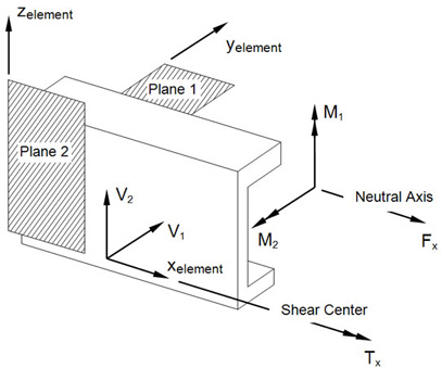
Figure 2. CBEAM Internal Element Forces and Moments