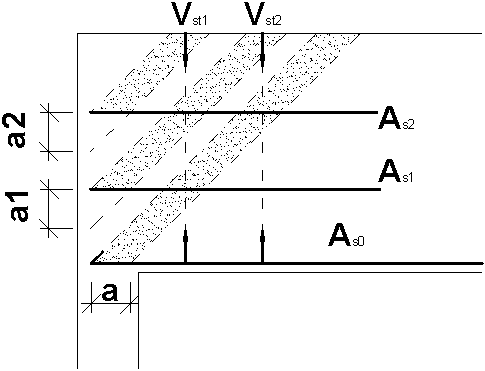
Robot allows calculations and verification of struts near supports in beams calculated according to BAEL, applying the following assumptions:
- the program checks the capacity of the concrete strut of the width resulting from the support width (i.e. without the use of the extra reinforcing bars above the support)
- the program checks the capacity of main bottom bars; these bars should carry the force equal to the support reaction
- if any of the conditions above is not satisfied, it is necessary to generate additional extra reinforcing bars above the support that allow increasing the width of the compressed concrete strut (i.e. bielles multiples).
Calculations of concrete struts are performed separately for the bottom strut and for top struts created by adding the extra reinforcing bars above the support.
The adopted calculation method assumes that the bottom strut carries the maximal allowable part of the support reaction considering its size and reinforcement, while top struts - the remaining part.
The capacity of compressed concrete struts is calculated form the formulas:
sbc lim = 0.8 * f cj / g b for fc,28 ≤ 40 MPa
![]() for f c,28 > 40 MPa
for f c,28 > 40 MPa
The algorithm for verification of the capacity of struts is as follows:
- The program calculates a force that the bottom strut is able to carry; a value of this force is limited by stresses in concrete (depending on its dimensions and the concrete strength) and by the capacity of bottom (main) bars; however, the force that is carried by the bottom strut may not be less than one-third of the total near-support reaction
Vu0 A = A s0 * fe / gs - steel strength
Vulimbc = 0.5 * s bc lim * b * a - concrete strength
V u0 = min (Vu0 A , Vulimbc )
- The remaining part of the force must be carried by additional struts
V ub = V u-Vu0
- Additional struts are created by adding successive layers of the extra reinforcing bars above the support; the size of a single strut is limited by:
- allowable width a (the strut width may equal a*SQRT(2), maximally)
- capacity of a single group of the extra reinforcing bars above the support (it is assumed that it is compressed concrete failure that occurs first, not tensile steel failure)
- distance to a group of the extra reinforcing bars above the support on the lower level
- In calculations, only these struts in case of which the extra reinforcing bars above the support are positioned below the allowable height, are taken into account:
a addmax = min (2/3 d; d-a)
- Stresses in the bottom strut are calculated according to the formula:
sbc = 2 * Vu0 / a / b
- The required section of the bottom reinforcement is as follows:
A s0 ≥ V u0 * g s / f e
- Stress in top struts equals:

where ai is a distance between two neighboring levels of the extra reinforcing bars above the support (measured downwards) taking account of the conditions mentioned in point 3
- The global section of the extra reinforcing bars above the support must equal:
SA s ≥ V ub * g s / f e
- The capacity of stirrups near the support undergoes verification. The program checks the condition of transfer of a part of the support reaction (Vub) to the higher levels of concrete struts (activated by adding extra horizontal reinforcing bars). Stirrups are verified on the segments that are projections of the width of top struts onto the top edge of the beam. The section of stirrups is verified separately for each strut and the force that must be carried by stirrups distributed on the width of a given strut equals:

This value is presented on the result layout, on the Area tab as a reinforcement area for shear force Ast_strut.
