This option allows you to design of RC elements within the defined structure model.
Access
- Click Design
 Provided Reinforcement of RC Elements
Having calculated the forces operating within a structure, you usually go on to the stage of designing particular structure elements. After selecting the RC elements and clicking the Provided Reinforcement of RC Elements option, Robot start to analyze the selection of elements. Based on the RC element type and its properties (such as geometry, coordinate system and support method), it transfers each element to the corresponding RC module. RC elements are transferred in the following order:
- Columns
- Continuous footings
- Beams
- Deep beams
- Walls
- Slabs
- Spread footings (foundation).
After completing the transfer, Robot displays the Parameters of RC Elements dialog (as in the image below), where you can select combinations, grouping type and so on.
The above dialog displays for RC beams. Other RC element types have their specific dialogs. After you specify and accept the settings in this dialog, the transferred elements are removed from the selection of elements for transfer to RC modules.
If definitions of transferred RC elements include errors, Robot may be unable to assign them to appropriate modules and displays an error message.
Column
Relevant loads transfer to the column and are displayed in the Loads dialog box.
In this dialog you can determine the type of loads to be transferred. These are either Simple cases or Manual combinations.
Apart from load values and natures, the Group field contains the number of the bar from which a load is transferred.
To enable moving to the RC column design module, the following conditions have to be satisfied:
- The element must be a bar.
- The element must be parallel to the Z axis of the global coordinate system.
- The element must be assigned a column cross-section.
If a group of columns is to be designed together (calculations result in one column type for all columns of the group), select the columns and choose one of the grouping types:
According to story. Based on structure geometry , the structure is divided into stories. On their basis levels are created in the calculation tree of the beam and column modules which ascribes elements to the relevant level.
According to geometry. Currently only available to columns. Elements of the same geometry are treated as one calculation element. It is designed for many combination groups resulting from loads acting on individual elements. All elements are designed for the most unfavorable arrangement of loads. The dialog for loads displays as many load groups as there are selected columns. A resultant column, capable of resisting the load belonging to each group is available after calculation. Identical column geometry (section and height) and identical column support conditions are required for the group to be calculated.
Column Chain. Columns positioned one over the other when the top node of the lower bar is simultaneously the bottom node of the upper bar are a column chain. Simultaneously, selected columns are automatically assigned their upper columns.
If several grouping options are selected simultaneously, there is a check for the possibility of grouping columns in the form of a chain. If it cannot be done, then they are checked for geometry, and finally for story.
Beams/Continuous Footings
Relevant loads transfer to the beam and are not displayed in the Parameters of RC Elements dialog.
In the case of continuous footings, displacements transfer as well as the elastic foundation coefficient Kz.
To enable moving to the RC beam / continuous footing design module, the following conditions have to be satisfied:
- The element must be a bar.
- The element must be assigned a column cross-section.
- The element must be defined as a bar on the elastic ground (this condition applies only to the transfer to the RC continuous footing design module).
In this dialog you can determine the type of loads to be transferred. These are either Simple cases or Manual combinations.
- Select Simple cases to calculate with code combinations according to the regulation of the design of RC structure elements. This is in the *.rgl file in the CFG folder.
- Select Manual combinations to calculate for the combinations defined in Robot. Apart from that, there appears the list of all manual combinations and you may select them.
The Grouping type field contains options that allow you to automatically group elements according to certain criteria (this does not work for continuous footings).
According to story. Based on structure geometry , the structure is divided into stories. On their basis levels are created in the calculation tree of the beam and column modules which ascribes elements to the relevant level.
According to geometry. Currently only available to columns. Elements of the same geometry are treated as one calculation element. It is designed for many combination groups resulting from loads acting on individual elements. All elements are designed for the most unfavorable arrangement of loads.
The Supports tab determines which adjoining elements are treated as supports for the indicated beam. This has direct bearing on the type and shape of reinforcement in the beam in question.
At the very bottom, the Supports tab displays a table of adjoining elements (bar number accompanied by a section label).
Supports in the form of columns are identified automatically.
Deep Beams
A panel (or a series of neighboring panels) is transferred to the design module along with the results of required reinforcement areas.
To enable moving to the RC deep-beam design module, the following conditions have to be satisfied:
- A deep-beam must be in the form of a rectangular panel and set in the vertical plane.
- It is possible to design neighboring panels (multi-span deep beam)
- openings should be defined as openings in the panel (and not by defining a panel of a complex shape). Openings may not touch panel edges and should be rectangular, however, slight deviations are acceptable (as long as the opening area does not differ from the area of the rectangle circumscribed on the opening more than 10 percent).
- Shell reinforcement types should be defined as compression/tension.
- A deep-beam is only partially supported along the bottom edge.
- If nodal supports are defined at neighboring nodes positioned on the horizontal panel edge, the distance between the outermost supported nodes is assumed as a support width.
- If a single nodal support or a support in the form of a bar (RC column or beam) is defined, its width will be taken into account. In the case of a nodal support, it is possible to define it as a column of a given dimension.
Walls
Robot transfers automatically loads at the center of gravity of the cross-section of the wall base to this module. Loads are presented on the Loads layout on the Reduced tab. Reduced loads are calculated based on FEM.
To enable the RC wall design module, the following conditions have to be satisfied.
- A wall must in the form of a single rectangular panel and set in the vertical plane.
- A wall must be supported along the entire bottom edge.
- Openings should be defined as openings in the panel (and not by defining a panel of a complex shape). Openings must be adjacent only to horizontal edges. An opening should be rectangular, however, slight deviations are acceptable (as long as the opening area does not differ from the area of the rectangle circumscribed on the opening by more than 10 percent).
For walls grouping According to story is possible (see the description for RC beams).
Foundations
The RC foundation design module has the reactions of a given support that consists of the load applied to the footing. Reactions are ascribed to the top level of the column pier and are displayed in the Foundation - loads dialog.
The foundation design module makes it possible to:
- When importing simple cases, present regulations that will be used during generation of combinations in the modules. The code regulation of the design of RC structure elements and the geotechnical regulation are presented.
- Select simple cases from the list of available cases.
- Display abbreviated and full names of simple cases, including moving load and time history analysis cases.
- Display the combination type for manual combinations (defined by the user).
- Consider cases of non-linear analysis (and non-linear combination) as design combinations.
At the bottom of the dialog are tools to determine the type of loads to be transferred. These are either Simple cases or Manual combinations.
- Select Simple cases to calculate with code combinations according to the regulation of the design of RC structure elements. This is in the *.rgl file in the CFG folder.
- Select Manual combinations to calculate for the combinations defined in the Robot program. Apart from that, there appears the list of all manual combinations and you may select them.
Supports are transferred to the module based on the following principles (automatic grouping of supports):
-
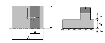
If exactly two supports are selected and you choose RC Foundation Design, you will be prompted to specify if one spread footing with two columns is to be designed. If so, the following geometrical dimensions will be read from a structure model: the distance between the axes of columns e2 (it cannot be modified) and the default dimensions of a foundation pier a 1, a 2 , b 1 , b 2 .
From the structure model the program will also read values of the relevant forces corresponding to the values of reactions in the local systems of selected nodes.
Apart from load values and natures, the Group field contains the number of the bar from which a load is transferred.
If a group of nodes is selected, the reactions originating from particular structure nodes intersect. Their names will display in the Group column. If a group of foundations is designed, the process will result in the calculation of a foundation that meets the conditions for all the selected support nodes.
The reactions transferred to the Foundations module are reactions in the local structure coordinate system. It is important in the case of spatial structures with differentiated column orientation.
-
If a group of supports under edge of the panel are selected, design for continuous foundation will be made in the RC Foundation Design.
If so, the distance between the external nodes will be set as a length (L) in the RC Foundation Design.
Loads from nodes (concentrated loads) will transferred to distributed loads taking into account distance between nodes. If node belongs to more than one panel, values of concentrated loads are divided at the number of panels.
Apart from load values and natures, the Group field contains the number of the node from which a load is transferred.
The Grouping field allows grouping of elements according to certain criteria:
-
According to story. Based on structure geometry, the structure is divided into stories. On their basis levels are created in the calculation tree of the foundation module which ascribes elements to the relevant level.
- According to geometry. Elements of the same geometry are treated as one calculation element. It is designed for many combination groups resulting from loads acting on individual elements. All elements are designed for the most unfavorable arrangement of loads.