This option analyzes punching in slabs resulting from loads from concentrated forces and reaction forces of slab supports.
This dialog allows the following.
- Viewing and defining the punching verification points.
- Grouping the verification points (unify the geometry).
- Assigning the supports (columns) geometrical properties of the head.
- Viewing the punching calculation results.
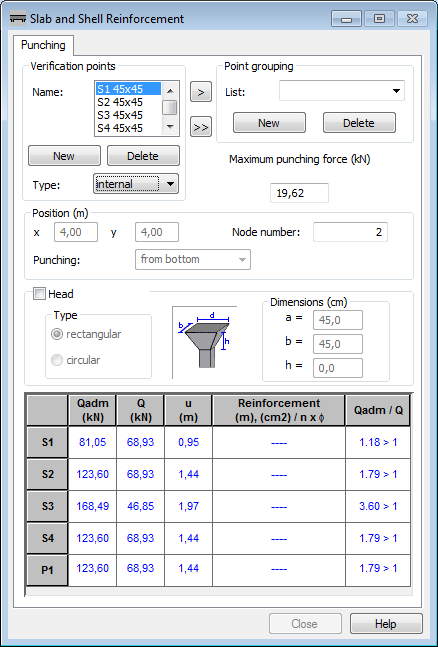
Viewing and Adding the User Defined Verification Point
If point supports are defined in a structure, they are automatically entered on the point list and denoted by the letter S with consecutive ordinal numbers. For each support type the following values display.
- Coordinates in the Position field.
- The node number of a support in the Node number field.
- Maximum reaction value of a support in the Maximum punching force field.
- Support geometry if defined during the support definition in the Advanced dialog box.
To display data of a selected verification point, select its name from the point list.
Independent from supports, verification points can be user defined.
To define a new verification point, click New in the Verification points field. Each time New is clicked, a verification point denoted by letter P and a consecutive ordinal number is added to the point list. Once a verification point is chosen, the definition fields of the point position, load geometry and values of punching force are active. These values are saved (no additional operation to confirm them is needed). To delete the added verification point, select it and click Delete. Points, which are the supports defined in structure geometry (denoted by the letter S) cannot be deleted.
Support (column) heads
You can define heads over supports (columns) considered in punching calculations. The Head option should be active (fields with the dimensions are available) and the head values should be defined. For the head on a rectangular support, these are the lengths of the head sides on the level where head meets the slab (denoted by the letters a and b) and the head height denoted by the letter h. For the heads over the circular supports these are d (head diameter) and h (head height for a circular head) or the lengths of the head sides (denoted by the letters a and b) for a rectangular head.
When the support belongs to a group, the head is applied to all elements of this group.
Point Grouping
Both the additional verification points and supports can be grouped to easily modify the geometry. Manually group points by selecting names and clicking >. Group all supports by clicking >>.
Additional verification points can be grouped if they have the same geometry type. In the case of supports, a compatibility of the support dimensions is necessary. If the compatibility conditions of the support dimensions are not satisfied, the verification points or supports (not compatible with the first listed) are deleted at group confirmation.
When points with different dimensions are grouped, dimension values are accepted based on the first defined point in the group. When a new point is added to the group, its dimensions are automatically changed to the be compatible with the group dimensions. Grouping the supports with different head dimensions is done by analogy.
When the group is defined, any change for the arbitrary group component relates to the entire group and is modified.
Presentation of Calculation Results
In the punching analysis for each verification point table, the following values are presented.
- Admissible punching force calculated according to the appropriate code requirements.
- Generalized design force defined in the Maximum punching force field for the additional verification points or read from FEM calculation results for supports.
- Critical circumference calculated on a base of code requirements.
- Reinforcement, which includes the following.
- Reinforcement range from member center in both perpendicular directions L1 and L2.
- Circumference of reinforcement zone (if required).
- Total area of reinforcement.
- Number and diameter of bars calculated on the total area and settings for punching.
- Safety factor being a ratio of a maximum punching force and admissible punching force.
Punching analysis results for individual points display in corresponding colors to the calculation result.
- Points that fulfill the conditions for punching and do not require reinforcement appear blue.
- Points that fulfill the conditions for punching and require reinforcement appear green.
- Points that do not fulfill the condition for punching despite applying reinforcement appear red.
The critical circumference is presented graphically on the Slabs - punching layout as a green line around columns. The range of punching reinforcement is shown graphically in a final drawing of a slab (formwork).
The dialog may include additional options depending on the selected code of RC structure design.
ACI Code
When selected, the Type option is also available. Each support determines its position either within slab, on slab edge or in slab corner. The support type is used during calculation of the admissible punching force [ACI 318 11.12.2.2].
EC2 Code
When selected, the b option is also available. For each support, the parameter determines the support position either within slab, on slab edge or in slab corner. A value of this parameter is used during calculation of the punching force [ENV 1992-1-1 EC2 4.3.4.3].
See also: