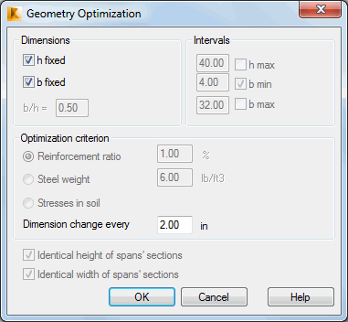
The options located in this dialog box enable optimization of geometry of a beam or a continuous footing with respect to average steel consumption per element. The dialog box presented in the figure below opens once the Geometry optimization button is pressed in the Calculation Options dialog box.

To perform an RC beam / continuous footing optimization, first a dimension that will be an optimized variable should be selected: h - height of a beam transversal section or b - width of a beam transversal section. Both dimensions may be variables simultaneously, however, defining the b/h dimension ratio is required then; this parameter will not change during optimization.
It is also possible to define maximum / minimum values (hmax and bmin/bmax) that determine a limit for increasing geometrical dimensions of a beam transversal section. If such limitations are not applied, then maximal values of these variables available in the program (10.0m) become the limit values.
There are two available criteria of beam geometry optimization:
- by reinforcement ratio
- by steel weight per concrete cubic meter.
While performing optimization, discretization is applied. The change value for an optimized variable value is determined in the Dimension change every field.
In case of multi-span beams, an additional limitation of optimization may be imposed by forcing identical transversal dimension of individual spans. It is possible to limit changes of one and of both dimensions.
- Final solution values may differ from the defined ones.It relates to the method of solving a problem applying discretization. This difference is strictly connected with the change value for section dimensions. Lower parameter value causes a result to be closer to the optimal result.
- It is possible to obtain different solutions of the same problem for the defined different beam initial dimensions; therefore, it is important to assume rational initial dimensions, as it ensures quicker calculations.
- Setting a little change value for a section and allowing for more freedom in setting both dimensions may result in the rapid growth of calculation time.
- The entire optimization issue is based on real (provided) reinforcement distribution. Thus, each solution satisfies all code requirements.