Once the Reinforcement Pattern command is called up and the 'Transversal Reinforcement' tab is selected, the dialog box shown below will appear on the screen.
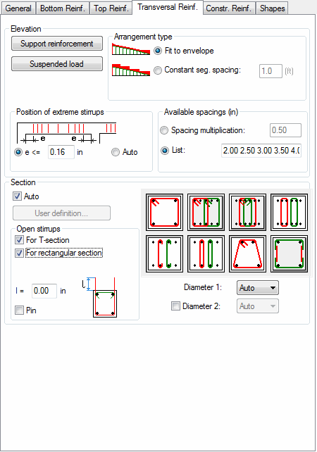
In the above dialog box, the user may define the transversal reinforcement selection method:
- by optimally customizing the reinforcement (diameter and spacing) to the envelope of shear forces (Fit to Envelope option).
- by using the jump method (Constant Segment Spacing option), i.e. the user defines the segment length on which shear force assumes a constant value equal to the maximal value in the given segment. Transversal reinforcement of constant spacing is selected for the given segment length and the constant shear force value.
The Available Spacing option allows defining the transversal reinforcement spacing criteria: by defining a value in the Spacing multiplication field, the user will receive the transversal reinforcement spacing as a multiple of this value. For example, by defining spacing multiplication as 5 cm, the reinforcement spacing will be 5, 10, 15, 20 cm, etc.
Another possibility consists in using the predefined spacing list (Caquot spacing is used as a default) that may be freely modified.
A user may also define the distance between a first stirrup and a support face taking advantage of the Position of extreme stirrups option.
The options located in this dialog box allow determining hang-load reinforcement. The following buttons are used for that (their pressing results in opening additional dialog boxes):
- Hang-load - to determine a hang-load
- upport reinforcement - options determining support reinforcement.
Options used to define the transversal reinforcement system on the beam section level are located in the Section field. The shape selection mechanism may be defined individually by the user with the User Definition option. For this option to be active, the precise number of reinforcement columns must be predefined on the General tab, namely; Nmin = Nmax. A separate dialog box with the general beam section view on which the transversal reinforcement is symbolically shown will then appear. Placing the cursor in the Bar List field and clicking in order on the transversal bars we are marking the shape and layout of the transversal reinforcement. The set shapes should be closed figures for the stirrups. The pin or shackle symbol is the a straight line connecting two longitudinal bars. Each defined shape should be confirmed by pressing the Apply button.
The following options are provided in the Open stirrups field:
- For T-section - if this option is switched on, it generates open stirrups in the case of a T-section
- For rectangular section - if this option is switched on, it generates open stirrups in the case of a rectangular section.
In the l = field the user should define the height of the stirrup part that extends above the top beam edge. If the Pin option is activated, it enables generation of a pin closing the stirrup opened from the top.
Another method of selecting the transversal reinforcement shape in the beam section is the AUTO option. The user selects the desired system from the suggested templates. It is also possible to define the reinforcement diameter. Diameter 1 pertains to the transversal reinforcement (first three templates), diameter 2 is assigned to the rest of the templates namely, pins and shackles. Due to this the user is able to freely define the reinforcement and the diameters of the individual types of transversal reinforcement.