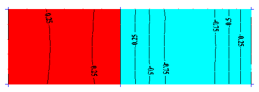
Use the Load Pattern - Loads dialog to display graphically the generated influence surfaces and the definitions of new cases and loads.
- Access
-
- Click Loads
 Special Loads
 Load Pattern.
 - Click Generate in the Load Pattern dialog.
- Click Loads
- Diagram of load patterns
- Contains the list of influence surfaces with the previously defined surfaces.
- Positive / Negative
- Specify which area of the influence surface should be displayed.
- Select Positive to display the areas which have a positive value, or Negative to display the areas which have a negative value.
- To improve readability, isolines and descriptions are also displayed on the diagram:
 Note: The default map colors for the positive and negative areas are specified in the Preferences dialog.
To change the default map colors,
- Click Tools
 Preferences
  Desktop Settings
  Range: plate diagrams.
 - Select Minimum values from the Element list if you want to change the negative values of the map, or Maximum values from the Element list if you want to change the positive values of the map.
- Click Color to open the color palette.
- Select a color, and then click OK.
- Click Tools
- Open a new window for selection
- Displays the diagram in a new view.
- Load definition
- This group allows you to define a new load case and a planar load on a contour.
- Load case name
- Enter a case name for the new load case.
- By default, the name of the currently selected influence surface is specified there.
- Add case
- Generates a new case with the specified name. Note: The generated case is added to the list of load cases for the current project.
- Load
- Opens the Uniform Planar Load (contour) dialog, which allows you to define the load intensity as well as the contour on which the load acts.