The option is used to define layers of the soil located under a continuous footing. The option becomes available once:
- the 'Soils'
 icon is pressed
 - the RC element / Soils command is selected from the menu.
When one of the above-listed options is chosen, the dialog box shown below is displayed on the screen.

After defining basic soil properties, all other parameters are calculated automatically and displayed in the table. The name field includes the list of predefined soils. Once one of them is chosen, the table is filled with data.
The table presents only these soil properties which are applied during calculations for a continuous footing.
The basic parameters of a soil may be changed, after accepting the new values, the remaining parameters will be automatically calculated and displayed in the table. The table fields, except for the fields containing basic parameters, are inactive.
The continuous footing module allows saving (the Save button enables it) a defined soil profile to be used in the calculators. The profile is saved as an XML database.
A soil profile contains all the data about soil parameters and may be freely transferred between work stations and used in other modules of the Robot program and calculators.
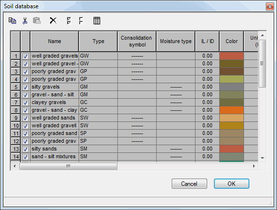
Once the Edit database button is pressed, the dialog box shown below appears on the screen.

This option allows a user to introduce a soil of any parameters to the available soil database.
Definition of a new soil should start with selecting one of the already-existing soils in the Name field. Once the cursor is out of that field, the program will read automatically the data characteristic of a given soil. After performing this operation, a user may modify freely parameters as well as a soil name.
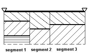
A soil located under a continuous footing may be divided into segments characterized by different soil layers. It is illustrated in the figure presented below. The segment geometry is defined by determining coordinates of the segment beginning and end in the top left part of the dialog box.

The elasticity coefficient calculated automatically for given soil conditions may be modified.
The program also allows defining the underground water level and the reference level. Moreover, it is possible to define values of the backfill thickness (on one or on both sides of the continuous footing). A vertical load due to the backfill soil is then calculated automatically by the program.
The Soil stress option determines the way how admissible stresses in the soil are adopted. If the calculated option is switched on, then a value of the admissible stress in the soil will be calculated automatically according to a code selected for soils defined in the table. The admissible option allows the user to determine their own value of the admissible stress in the soil.
See also: