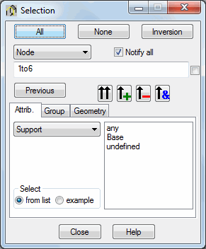
The Selection dialog is used to pick objects from the structure. It is accessed by selecting Edit > Select. It may also be activated for individual objects by clicking the following under the menu: ![]() node selection,
node selection, ![]() bar selection,
bar selection, ![]() load case selection, and
load case selection, and ![]() vibration mode. You can also select View > Filter while in the table.
vibration mode. You can also select View > Filter while in the table.

Options are similar for the node, bar, and load case object types. Other appear in the Selection dialog if Modes are selected.
To perform a selection, do the following:
- Indicate the object (node, bar, panel, solid, load case, mode, or others).
- Enter the corresponding numbers of the selected objects, or use the options found in the lower portion of the dialog.
The bottom of the Selection dialog depends on the object selected. Performance of the options available here is described based on node selection.
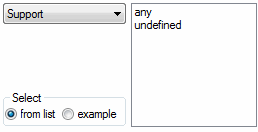
Nodes may be chosen using the node attributes (object) support, finite element, panel, solid, bar, compatibility, rigid link and emitter. They are selected in the right part of the dialog.
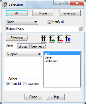
Selecting one of the types and clicking ![]() adds all support nodes (regardless of the support kind) to the selected nodes.
adds all support nodes (regardless of the support kind) to the selected nodes.
A checkbox for determining the definition of selection mode is found to the right of the list of selected nodes. If deselected, the field of node selection will display node numbers corresponding to the nodes where the support is applied.

If selected, the field of node selection will display Support = any.

The difference between the two buttons is as follows.
![]() - Adds selected objects to the selection.
- Adds selected objects to the selection.
![]() - Replaces the selection with numbers of the selected objects.
- Replaces the selection with numbers of the selected objects.
Two additional buttons are available.
![]() - Removes selected objects from the existing selection.
- Removes selected objects from the existing selection.
![]() - Finds a common part of the existing selection and a selected structure attribute (such as finding members that are assigned the section W 14x120).
- Finds a common part of the existing selection and a selected structure attribute (such as finding members that are assigned the section W 14x120).
The lower part of the dialog contains:
- List - objects for selection will be chosen from the list available in the right lower part of the dialog box
- Example - selection criteria based on the object type entered to the Value field.
Once Example is selected, the lower part of the dialog will change.

Enter the type of the selected attribute. For example, entering Steel for Material and Bar for Object will select all steel bars defined in the structure when ![]() is clicked.
is clicked.
The Selection dialog defines a group of nodes or bars. Once the selection is made, switch to the Group tab.

Once the selection is made and ![]() is clicked, the color and the name of the group can be defined. Click Apply to confirm and apply the information.
is clicked, the color and the name of the group can be defined. Click Apply to confirm and apply the information.
In the Selection dialog box you can select objects by means of a defined grid of structure axes. The Selection dialog includes an additional Geometry tab.

Here you can determine positions of the beginning and end structure axes (in all directions of the coordinate system), between which objects are to be selected.
Use the buttons in the dialog to:
- All - selects all objects.
- None - deselects the selected objects.
- Inversion - inverts the current object selection.
- Previous - selects all objects defined in the previous selection.
See also:
Table filtering (data and calculation results)