Use this dialog to specify parameters for a soil load.
- Access
-
- Click Loads
 Special Loads
 Soil Pressure.
- Click Loads
Soils Tab

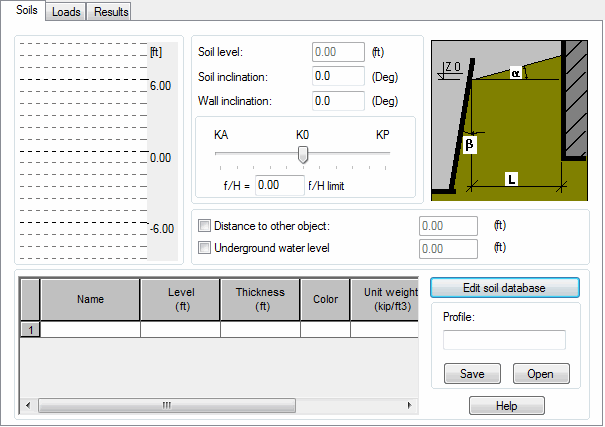
You can define the following parameters on the Soils tab:
- Geometrical data concerning a retaining element and soil
-
- Soil level
- Iidentifies the Z coordinate of the soil level position in a structure model. You cannot change this value, because it corresponds to the level of the first soil layer defined in the table.
- Soil inclination
- Angle of soil inclination to the a horizontal direction.
- Wall inclination
- Angle of the retaining element's deviation from the b vertical. Note: A value of the bangle for the Kp coefficient is preceded by (+) sign; whereas, for the Ka coefficient it is (-) sign, if the element is being inclined toward the ground.
- Distance to other object
- This distance should be specified if there is a reduction of pressure caused by other nearby objects that should be considered.
- Underground water level
- This value is specified in global coordinates (with respect to the soil level). The value should be defined if a reduction of pressure caused by the presence of underground water is to be considered. The position of the underground water level is displayed in the soil cross section. Remember: the presence of underground water affects a pressure value because of reduced soil compaction and water pressure.
- Data scale
- Data that specifies the soil work that results from the displacement of a retaining element. The displacement is defined using the rotation element r, which is assumed to be approximately equal to: f/H (wall top displacement / element height). The soil work mode can be determined as:
- Active pressure Ka -> ρa ≤ ρ < 0
- Static pressure Ko -> ρ = 0
- Passive pressure Kp -> 0 < ρ ≤ ρp
- Limit value or intermediate value.
- Table
- A table for defining soil layers.
- Select a soil type in the name column, and then specify a soil layer level in the Level or Thickness column.
- The table lets you access the soil database, which is the default database specified in the Job Preferences dialog. (You can edit the list of databases by clicking Tools > Job preferences on the Databases tab > Soil Database.)
- Diagram of the soil layers and depth scale.
- Enter a name in the Profile box, and then click Save to save the current profile as an XML file.
- Click Open to select an XML file.
- Edit soil database
- Click this button to open the Soil database.
Loads Tab

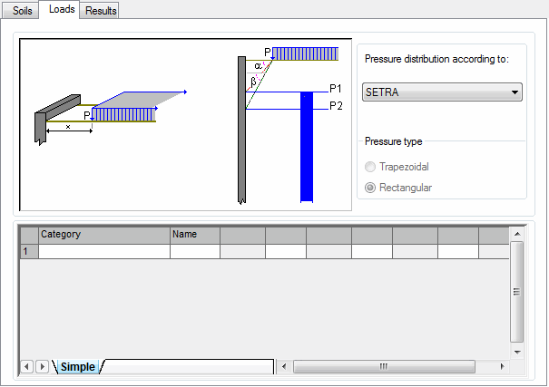
You can define external loads applied to soil on the Loads tab. The loads are defined in the table at the bottom of the dialog. Each load is assigned a name and a list of parameters depending on the load type. You can define the following load types:
- Linear load - The load is described by the following data: name, distance x [length], and load intensity Q [force/length].
- Distributed load - The load is described by the following data: name, distance x1 [length], distance x2 [length], and load intensity P [force/length^2].
- Uniform load - The load is described by the following data: name, distance x [length], and load intensity P [force/length^2].
You can also select a pressure distribution type associated with the following codes:
- Polish codes: PN-83/B-03010 and PN-85/S-10030
- French requirements: SETRA
- Russian code RD 31.31.27-81.
Results tab

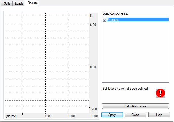
This tab displays:
- The right side of the dialog has a list of defined loads. The list displays a soil pressure load and user-defined cases resulting from loads applied to backfill. From this list, you select the cases that you want transferred as a load to the structure model.
- The left side of the dialog displays a soil cross-section with a load diagram. The diagram shows the case that is selected from the list. By moving your cursor over the diagram, you can read individual points on the diagram.
- Messages about incorrect data are displayed below the list.
Click Calculation note to open a text editor containing a set of data and pressure diagrams. Click OK to close the dialog and start the preparation for generating loads.