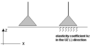
When the Rigid tab is selected from the Support Definition dialog, the following dialog displays.

To define a rigid support:
- Enter a name for the support label.
- Select fixed directions (blocked degrees of freedom) in the node:
- UX
- UY
- UZ
- RX
- RY
- RZ
Linear and planar supports can be defined in the global or local (compatible with the system of a panel or edge) coordinate system. (You cannot define nodal supports in a local coordinate system.) Also, you can define an uplift for each direction:
- None - No uplift
- + - uplift direction is the same as the axis direction (e.g. UX+)
- - - uplift direction is opposite to axis direction (e.g. UZ-).


A diagram of the support being defined is displayed in the lower right of the dialog. Clicking Direction under the diagram opens the Support direction dialog, where you can define the direction of the local x axis for the support. The axis is determined by specifying a point, a node, or rotating a support with respect to any axis in the global coordinate system.
Clicking Add, adds the support to the list of active supports.
Clicking Advanced, which is available for nodal and linear supports (it is not available for planar supports), opens a new dialog: Support definition - Advanced.