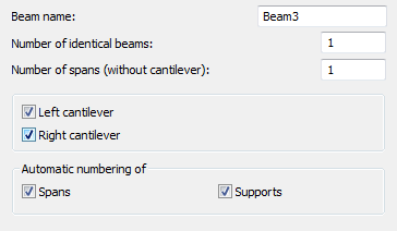
The dialog box shown below appears on the screen after defining basic data of an RC beam, selecting RC beam with varying spans and pressing the >> button.

The dialog box above enables definition of the following parameters:
- Beam name - field for defining a name of a whole beam
- Number of identical beams - field for specifying a number of identical beams to be defined (important in bills of materials)
- Number of spans (without cantilever) - field for defining a number of beam spans (right and/or left cantilevers are disregarded)
- Right and left cantilevers - if these options are switched on, then a cantilever is added on the left and / or right side of an RC beam
- Automatic numbering of spans and supports - if these options are switched on, then spans and /or supports of a defined RC beam are automatically given numbers (names).
After pressing theNext >button, the user moves on to the next dialog box where parameters of the cross sections for individual spans of an RC beam may be determined.
The following span types are available:
![]() left cantilever
left cantilever
![]() outermost span (left)
outermost span (left)
![]() middle span
middle span
![]() outermost span (right)
outermost span (right)
![]() right cantilever.
right cantilever.

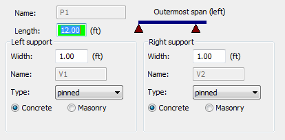
In the above dialog box the user may specify the name of a designed span (active span) and basic information about the span geometry: span length and parameters of span supports (width, name of the right and left supports, support type: pinned, fixed or roller as well as type of material from which the support is to be made: concrete support or masonry support). There are also the Torsion not consideredoptions available in the above dialog box. If they are activated, then for a selected support torsion will be ignored.
After pressing theNext >button the program proceeds to defining elevation parameters of the next span in an RC beam.
After defining elevation parameters of all spans of an RC beam and pressing the Next > button, the user moves on to next dialog boxes where parameters of cross sections for individual spans of an RC beam may be determined.

The options provided in the above dialog box depend on the options selected in the first dialog box (Consider compressed slab, Hollow slabs).
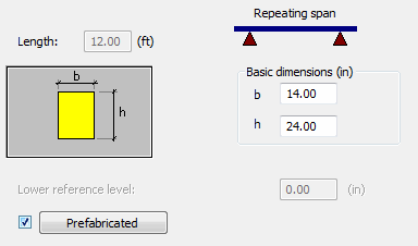
The drawing above presents the options for a rectangular section (the options Consider compressed slab, Hollow slabs are switched off).
In the upper part of the dialog box the information about the beam name and span length may be found (these fields are inaccessible in this dialog box).
In the dialog box above the user may define dimensions of an RC beam cross section: b (section width) and h (section height).
For the active optionsConsider compressed slab or Hollow slabs,the above dialog box shows additional parameters concerned with adjoining slabs (slab thickness, prefabricate thickness, slab overhang and lowering, support depth, etc.).
Activation of thePrefabricatedoption and pressing thePrefabricatedbutton opens an additional dialog box for defining the values of height and support depth of a prefabricated beam.
The right part of the dialog box contains, as well, the Lower reference leveloption; this edit field is used to define a value of the level of the beam bottom in successive spans in relation to the first span (the option is not available for the first span of a beam).
After pressing theNext >button the program proceeds to defining cross section parameters of the next span in an RC beam.
After completing definition of parameters and pressing the Finish button the program will create an RC beam with the parameters determined in the dialog box.