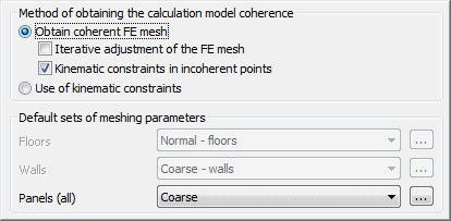
After clicking the Meshing option in the tree located in the left part of the window Job preferences the field shown below appears in the right part of the window.

Options to obtain coherence of the generated meshing of the finite elements are located in the top part of the dialog.
The program provides the following methods for obtaining consistent mesh of finite elements:
- by obtaining consistence of the mesh - after selecting this option, the existing finite elements are modified in such a way that the obtained mesh was consistent; if incompatibility occurs in verification of the consistence of the mesh, a new mesh of finite elements is generated in the spots where the mesh is not adjusted; the program allows using two methods:
- iterative adjustment - local meshing of panels for which inconsistencies of the mesh occurred is activated
- kinematic constraints in inconsistence points - the method using the kinematic constraints to unite nodes.
- by using kinematic constraints - the method assumes that the meshes for the particular panels do not undergo adjustment (checking the consistence of the meshes is not activated). The nodes are united by means of kinematic constraints; if the option is activated, it is possible to define default dimensions of the finite elements for some types of panels (slabs, walls).
Uniting meshes of the finite elements and the structure nodes by the use of the kinematic constraints consists of interpolation of the displacement of the connected node on the base of shape function of the element the node is united with.
The options allowing to select type of the created finite elements mesh for the structure elements (slabs, walls, panels) are located in the bottom part of the dialog. The following sets of the meshing parameters are available: coarse, normal, fine and user-defined).
Clicking one of the keys (...) located on the right side of the sets of the meshing parameters' results in opening of an additional dialog where the parameters of the surface or volumetric FE mesh generation can be defined.
See also: