Use this connection type to design and verify tube connections of steel members with sections of round, square, and rectangular tubes according to the guidelines of Eurocode 3: 2005.
Connection calculations cover tube connection types K, N, KT, T, Y, and X. You can use I-sections as a chord in the connection, and can use brackets of the chord (horizontal plates, lateral plates) welded to the chord (as shown).

Calculation methods:
The set of forces considered during calculations of the connection:
- axial forces and moments in the truss chord
- axial forces and moments in adjoining bars (diagonals)
- axial force and moment in the truss post.
Capacity verification
Methods applied for calculation of the capacity of individual bars in a connection have been developed based on the guidelines:
- included in Eurocode 3: EN 1993-1-8:2005
- publications released by CIDECT
- Design Guide for Hollow Structural Section Connections
- Design Guide for Rectangular Hollow Section (RHS) joint under Predominantly Static Loading.
Weld design
It has been assumed that the check of a node capacity through assessment of the capacity N Rdi using butt welds is equivalent to the check of a capacity of these welds. Therefore, during verification of welds, they are treated as fillet welds. The check of a weld capacity proceeds according to the guidelines in Eurocode 3: 2005.
It has been assumed that
- for nodes made entirely of tubes with a round section or with chords made of I-sections
- and for diagonals and posts made of tubes with a round section
the length of welds equals their real length.


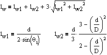
If the tube meets the flat element at an angle
If chords are made of rectangular and square tubes, it has been assumed that some segments of welds are ineffective.
K and N connections
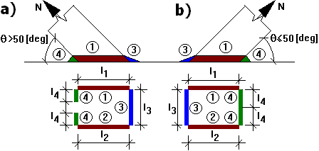
For a connection in which there is a distance between bars, it is assumed that longitudinal segments of welds (with respect to the chord axis) are fully effective, while effectiveness of transversal segments differs. Segment 3 (internal weld) of the inclined bar joint participates in the transfer of a force from one bar onto the neighboring segment. Segment 4 (external weld) is excluded from participation if there are large inclination angles.

Design sections of fillet welds:
a) design section of a weld for θ > 50 [deg]
b) design section of a weld for θ ≤ 50 [deg]
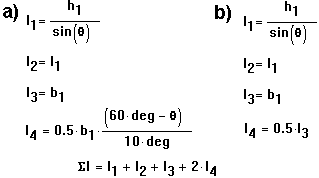
The effective length of welds in the K and N connections equals:

The value l4 in the interval (50deg, 60 deg) should be interpolated linearly.
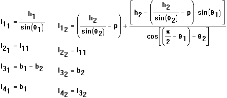
For a connection where bars overlap, it is assumed that welds are considered on all 4 edges of connected tubes, while their lengths are calculated according to real dimensions in the connection.

Lengths of welds in the K and N connections equal:

The procedure when calculating stresses on individual segments of welds is identical to that for a connection with a distance between bars.
See also:
T, Y, and X connections
Segment 3 is not effective if values of b are small.
It is assumed that the weld length is effective:
