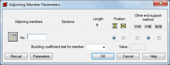
To define the parameters of adjoining members when calculating the buckling coefficient of the main member, click
![]() , in the
Buckling Diagrams dialog.
, in the
Buckling Diagrams dialog.

Enter the following information for the main member:
- The number of the consecutive structural members ( the section for the selected structure member is automatically entered); enter the member number in the appropriate field or select the member on the screen.
- Position (placement) of the member in the structure; two methods are possible: vertical
 or horizontal
 .
.
For several codes (ADD8, Eurocode3, NEN6770/6771, PN90) another parameter is included: the support method for the opposite end of the adjoining member. The available support types depend on the selected steel code requirements.
Once the adjoining member of a selected number is in place, the buckling coefficient value is available in the lower portion of the dialog. The value of the buckling coefficient is located in the Member Test Value field once the adjoining member number is selected.
To manually define the parameters of adjoining members, press the Manual button found in the lower part of the dialog. The manual definition of the adjoining member parameters will display in an additional window..
To define parameters of varying inertia members, press the Parameters button to and enter the information on the additional dialog.