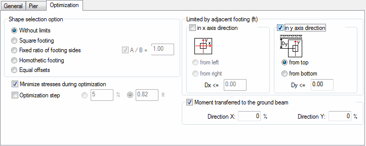
The Optimization tab allows you to define the shape and dimensions of a designed foundation.
Access
Select RC Design  Provided reinforcement layout, and then create a new RC element, or open an existing one.
- Click RC Element
 Dimensions.
 - Click
 (Dimension Definition).
Dialog elements

- Shape Selection Options
-
These options define particular properties of the foundation geometry which will be chosen in the design process. The Fixed option located next to the footing dimensions must be deselected to modify Shape Selection options.
- Without limits -General form of the footing geometry without any geometric correlations.
- Square footing - Calculations and foundation geometry optimization result in a square footing.
- Fixed ratio of footing sides -Obtain the values of footing length and width whose ratio is fixed. The quotient of the lengths of footing sides (A / B) is specified when the Fixed ratio of footing sides option is selected
- Homothetic footing - Footing dimensions depend on column dimensions. The proportion between footing dimensions and column dimensions is maintained according to the following ratio: a / b = A / B
- Equal offsets - Obtain equal depth of footing offsets in all directions.
Optimization parameters are defined in the middle of the dialog if the adopted dimensions of the foundation do not meet the requirements (in particular, the foundation dimensions that are optimized include: A, B and h1).
- Optimization step
-
After selecting the Optimization step option, an optimization method should be chosen.
- Specified length (m).
- Percent value of the dimension used so far (%).
- Limited by adjacent footing
-
This field defines the minimal distance to maintain between the column/wall axis and the edge of the neighboring foundation or other object. This limit enables control of the selection of the foundation shape (to optimize its geometry) so its edge does not interfere with a neighboring object.
This option operates in connection with the shape-selection options, defining the limits in any direction and on any side of the foundation. It is active when the Fixed options for footing dimensions are deactivated. In special cases, it is possible to define the limits in the X and Y direction.
- Moment transferred to the ground beam
-
You can do basic modeling of the ground beam and the way in which a part or entire bending moment is transferred while checking the condition for overturning.
- Direction X field. Value of a part of moment being transferred to the ground beam in the X direction (0% means that for a given direction the ground beam is not considered)
- Direction Y field. Value of a part of moment being transferred to the ground beam in the Y direction (0% means that for a given direction the ground beam is not considered).
Note: In spread footing design a part of bending moments carried by ground beams is disregarded.