Load Capacity of the soil is a core limit state of foundation design, therefore it may not be turned off during the design or analysis of a foundation. The analysis of this state consists of comparing the maximum value of the force or the stress resulting from external loads to allowable values. Allowable values are user-defined or calculated based on soil parameters.
When values are calculated, there is the possibility of layered soil analysis. User-defined values of allowable stresses are compared to those directly under the foundation base.
User-defined load capacity of the soil is compared to:
- The maximum value of stresses under the foundation or the average value after activating the Plastic stress redistribution option in the Calculation options tab for ACI \ BS 8004:1986 \ CSA \ ENV 1997-1:1994 (EC 7), EN 1997-1:2004 (EC 7)
- The maximum average value for DTU 13.12 \ Fascicule 62 Titre V \ SNiP 2.02.01-83
- The average value and the maximum value divisible by 1.2 for PN-81/B-03020.
Calculations for individual codes
- ACI \ BS 8004:1986 \ CSA
There have been several basic methods of calculating load capacity of soil presented in studies. The calculations in these methods compute allowable stresses in the soil or the allowable force corresponding to them. Chronologically, these methods are: Terzagi (1943), Meyerhof (1963), Hansen (1970), Versić (1973, 1975). Hansen is employed along with the guidelines for it presented in studies.The basic formula for the load capacity by Hansen:
It has been limited to cases analyzed in the spread footing module. Factors responsible for footing inclination b and backfill slope g equal 1.0 are assumed.
Since it is not allowed to use soils of friction angle φ = 0.0 degrees in the module, only the first of the formulas by Hansen is applied. The final formula for calculation of allowable stresses for ACI \ BS 8004:1986 \ CSA is:

where the relevant factors are equal to:
and the effective area A' = B' * L'.
where:
The calculated value qult divided by the safety factor SF=3.0 is compared to the maximum average stress in the soil, induced in SLS:

- DTU 13.12 and Fascicule 62 Titre V
For French codes the following calculation methods of load capacity of the soil are available:
Laboratory
Calculations for both codes are performed according to section 3.21 of DTU 13.12 (Fascicule does not provide guidelines concerning the laboratory method).
The general load capacity condition is expressed as follows:
 .
.
This assumes that qref denotes the greatest average stress occurring under the foundation in ULS, while gg is a coefficient equaling 2 for ULS combination and 1.5 for ULS combination including wind loads.
Load capacity calculations proceed as follows:
 .
.
Non-dimensional load capacity coefficients equal:
 .
.
Non-dimensional shape coefficients equal:
 .
.
Non-dimensional coefficients of inclination of a load induced by the H horizontal force equal:
 .
.
Full Pressiometric
Calculations are based on a user-defined curve as a result of on-site pressiometric research. Soil type is a significant parameter on the reference level of the foundation. The soil type determines coefficients used in the calculations of load capacity and are adopted based on appendix E.1. of Fascicule 62 Titre V
- DTU 13.12
The general load capacity condition can be expressed as follows.
(analogously as in the laboratory method) .
Calculations of the load capacity value qu are performed based on section 3.22 of the code in the following way:
 .
.
These are adopted according to the code and p le * is an equivalent limit stress calculated from the formula:
where B is a dimension of the foundation in the considered direction.
The foundation depth is assumed as the minimum foundation depth Dmin less the depth d (the disregarded part of the foundation depth).
- Fascicule 62 Titre 62
The general load capacity condition can be expressed as follows:
 .
.
All values in the above formula are adopted according to the formula, based on section B.3.1,1 as well as the appendixes B.1., E.2., F.1.
Stress Pressiometric
The soil load capacity for this method is adopted based on a user-defined value. The user-defined allowable (characteristic) qu value, ULS or SLS, is always converted to the characteristic value qu, and next, based on that value the limit stress value qlim is calculated according to the formulas:
DTU 13.12
Fascicule 62 Titre 62
 .
.
If rectification is selected, rectification of a user-specified value due to geometry and loads is performed. A user-specified value is treated as the load capacity qu for the foundation with the unit dimensions (A=B=1m) which is subjected only to vertical loads, with the foundation depth (Dmin - d). Real dimensions of the foundation, such as the influence of horizontal loads and moments (eccentricities) are taken into account. This is reflected in calculations of the coefficients kp, idb. Soil type is a significant parameter on the reference level of the foundation. The soil type determines coefficients used in the calculations of load capacity and is adopted based on appendix E.1. of Fascicule 62 Titre V
- DTU 13.12
- ENV 1997-1:1994 (EC 7)
Analysis of the load capacity of the soil is based on points 6.5.1, 6.5.2 and Appendix B to code EC 7. The general load capacity condition V d < Rd can be made more rigorous by introduction of a safety factor greater than 1.0 in the Geotechnical Options dialog box on the General tab.

Load capacity value calculation proceeds as follows.
- For conditions with drainage, formula B.2:

Dimensionless factors of the load capacity are equal to:
 .
.
Dimensionless factors of the shape are equal to:
 .
.
Dimensionless factors of the load inclination resulting from the horizontal force H parallel to the longer and to the shorter sides, respectively, are equal to:
 .
.
Coefficients of the foundation depth equal:
where:
.
- For conditions without drainage, formula B.1:
 .
.
Dimensionless factor of the shape is equal to:
sc = 1.2 + 0.2 * ( B' / L' ).
Dimensionless factor of the load inclination resulting from the horizontal force H is equal to:
Note that the soil parameter: Cohesion without drainage - c u is applied here.
- For conditions with drainage, formula B.2:
- EN 1997-1:2004 (EC 7)
Analysis of the load capacity of the soil is based on points 6.5.2.1, 6.5.2.2 and Appendix D to code EC 7. The general load capacity condition V d < Rd is multiplied by the g R coefficient depending on the calculation approach. The coefficient can be modified in Job preferences. The load capacity value calculation is carried out in the following way:
Load capacity value calculation proceeds as follows.
- For conditions with drainage, formula B.2:

Dimensionless factors of the load capacity are equal to:
.
Dimensionless factors of the shape are equal to:
.
Dimensionless factors of the load inclination resulting from the horizontal force H parallel to the longer and to the shorter sides, respectively, are equal to:
Coefficients of the foundation depth equal:
where:
.
- For conditions without drainage, formula B.1:
.
Dimensionless factor of the shape is equal to:
sc = 1.2 + 0.2 * ( B' / L' ).
Dimensionless factor of the load inclination resulting from the horizontal force H is equal to:
Note that the soil parameter: Cohesion without drainage - c u is applied here.
Partial coefficients for EN 1997-1-1:2004 (EC 7)
For the EN 1997-1-1:2004 code, there is a possibility to modify the partial coefficients for the R (pressure and resistance) and M (soil parameters) sets 2.4.7.3.4.
Default values of the parameters can be found in the Job preferences.
A sets (for actions or their effects) of partial coefficients are available in the regulations for the geotechnical code combinations (EC7_2004_geo.rgl).
- For conditions with drainage, formula B.2:
- PN-81/B-03020
Soil load capacityanalysis is based on point 3.3.3, Appendix 1. The general load capacity condition:

can be made more rigorous by introduction of a safety factor greater than 1.0 in the Geotechnical Options dialog box on the General tab.

Calculation of the load capacity value proceeds as follows (Z1-2):
 .
.
Dimensionless factors of the load capacity are equal to:
 .
.
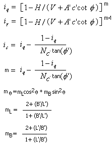
Dimensionless factors i are determined on the basis of the code nomograms (fig. Z1-2).
- SNiP 2.02.01-83
Analysis of soil load capacity is based on point 2.58 -2. The general load capacity condition (11) is:

where:
γ c - environment coefficient
γ n - reliability factor taking account of the use for which a structure is intended
Both coefficients are modified in the Geotechnical Options dialog by the formula presented there:
 .
.
As a result of design the reliability factor of a structure is obtained, which equals:
 .
.
Calculation of the load capacity value proceeds as follows (16):
 .
.
Dimensionless factors of load capacity N are calculated according to table 7 of the code. Linear interpolation between values is performed. The dimensionless factors of shape x are calculated as follows (17):
 .
.